Synchronizing clock signals of server and client devices in a network system based on power source synchronous pulse signal

a technology of synchronizing clock signals and power source pulse signals, applied in the direction of synchronisation signal speed/phase control, color television with bandwidth reduction, television systems, etc., can solve the problems of change and delay of transmission time, delay of transmission tim

Inactive Publication Date: 2007-08-28
D & M HOLDINGS INC
View PDF6 Cites 139 Cited by
  • Summary
  • Abstract
  • Description
  • Claims
  • Application Information

AI Technical Summary

Problems solved by technology

However, when the data are transmitted through the communication line, it must cope with a change and a delay of transmission time.
The change and the delay of the transmission time are also caused when such plural electronic devices are connected and utilized.

Method used


Image

  • Synchronizing clock signals of server and client devices in a network system based on power source synchronous pulse signal
  • Synchronizing clock signals of server and client devices in a network system based on power source synchronous pulse signal
  • Synchronizing clock signals of server and client devices in a network system based on power source synchronous pulse signal

Examples


first embodiment

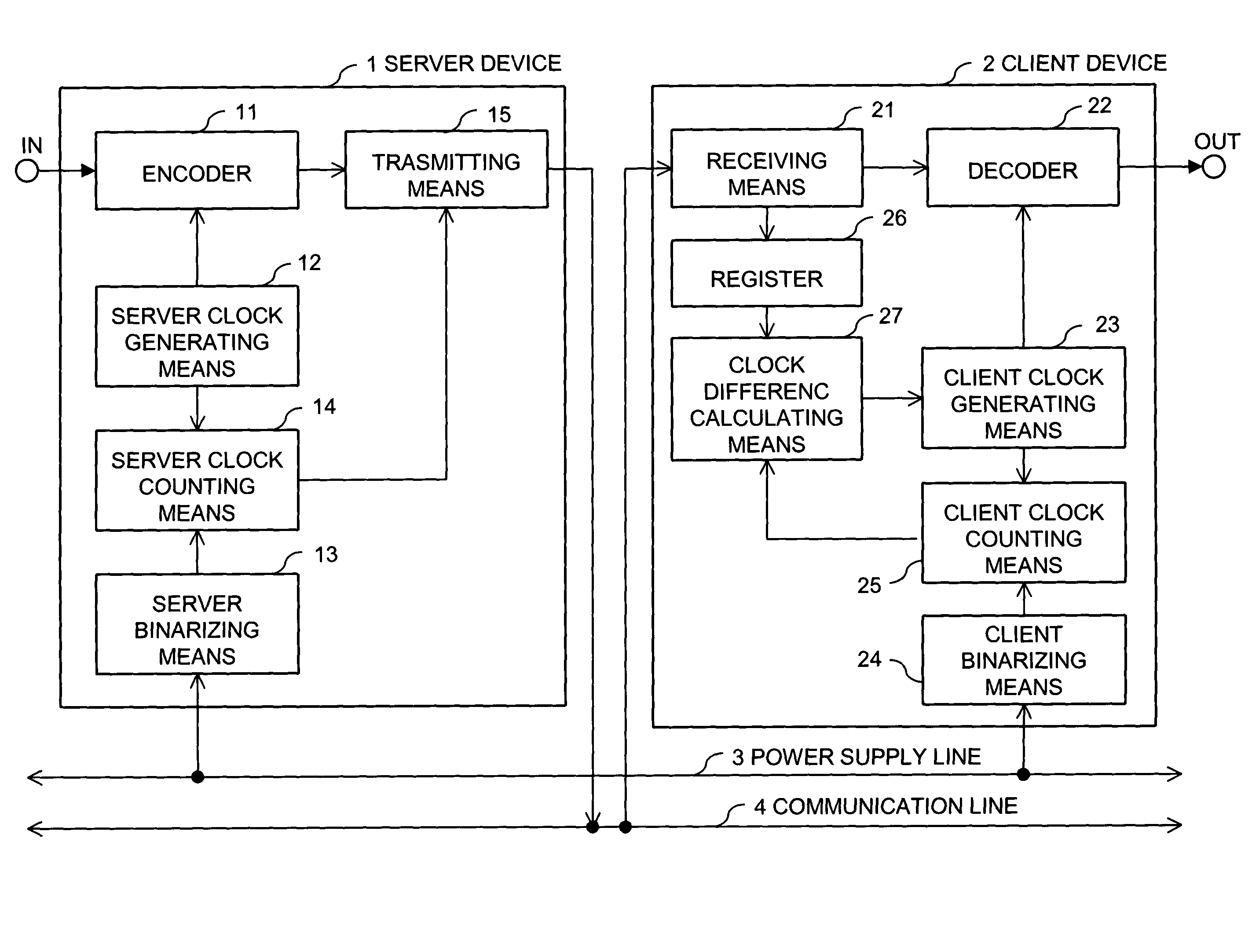
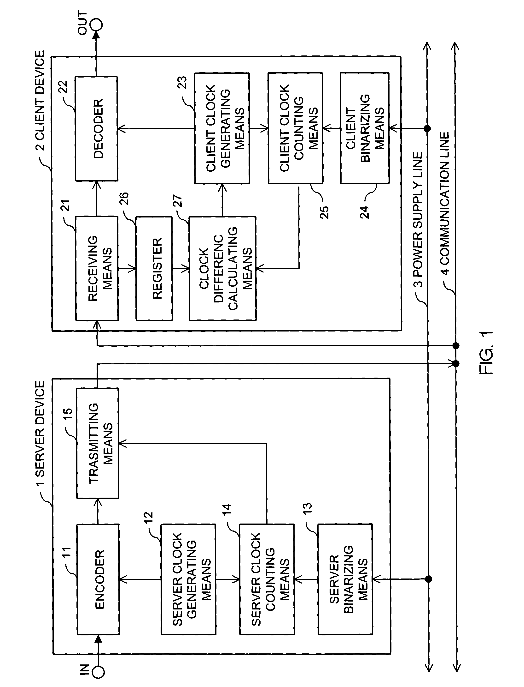
[0025]FIG. 1 is a block diagram showing the construction of a network system of the invention.

[0026]A server device 1 encodes and compresses audio information or video information inputted from an input terminal IN, and transmits the compressed information to a client device 2 through a communication line 4. The client device 2 receives the audio information or the video information from the server device 1, and decodes and decompresses the audio information or the video information, and outputs the decompressed information to an output terminal OUT. A power supply line 3 supplies electric power to the server device 1 and the client device 2. The communication line 4 is connected to the server device 1 and the client device 2, and transmits the audio information or the video information, etc. The server device 1 and the client device 2 are operated as the network system of the push type.

[0027]The server device 1 has an encoder 11, a server clock generating means 12, a server binariz...

second embodiment

[0047]the invention will be explained.

[0048]FIG. 5 is a block diagram showing the construction of the second embodiment of the network system of the invention.

[0049]A server device 1 encodes and compresses audio information or video information inputted from an input terminal IN, and transmits the compressed information to a client device 2 through a communication line 4. The client device 2 receives the audio information or the video information from the server device 1, and decodes and decompresses the audio information or the video information, and outputs the decompressed information to an output terminal OUT. A power supply line 3 supplies electric power to the server device 1 and the client device 2. The communication line 4 is connected to the server device 1 and the client device 2, and transmits the audio information or the video information, etc. The server device 1 and the client device 2 are operated as the network system of the push type.

[0050]The server device 1 has an...


PUM


Abstract

In a network system, clock signals of a server device and a client device are synchronized with each other without having any influence of a change and a delay of the transmission time of data. Therefore, in the network system in which the client device receives and reproduces information transmitted from the server device, the server device counts the number of clock pulses of a server clock signal used to compress and encode information on the basis of a power source synchronous pulse signal synchronized with a power source frequency. The server device outputs information showing the counted clock pulse number and the compressed and encoded information to the client device. The client device counts the number of clock pulses of a client clock signal used to decode and decompress the compressed and encoded information on the basis of the power source synchronous pulse signal synchronized with the power source frequency. The client device conforms the frequency of the client clock signal to the frequency of the server clock signal on the basis of the clock difference between the clock pulse number received from the server device and the counted clock pulse number.

Description

BACKGROUND OF THE INVENTION[0001]1. Field of the Invention[0002]The present invention relates to a network system for transmitting audio information, video information, etc.[0003]2. Description of the Related Arts[0004]The case of possessing plural personal computers (the personal computer hereinafter is called “PC”) in one household, and constructing and utilizing a PC network within a home is increasing. Further, a utilizing method for accumulating audio information, video information, etc. in a server device by using the PC network within the home, and reproducing the audio information, the video information, etc. by a client device is considered.[0005]As one example of the utilizing method of the network within the home, there is a method for utilizing Transmission Control Protocol / Internet Protocol (hereinafter called “TCP / IP”) as a communication protocol of the network, and compressing and transmitting the audio information, the video information, etc. in a Moving Picture Expe...

Claims


Application Information

Patent Timeline
Patent Type & Authority Patents(United States)
IPC IPC(8): H04J3/06H04N7/12H04L12/28H04L7/00H04L7/04H04L29/06
CPCH04J3/0644H04L47/10H04L47/2416H04L47/26H04L47/30H04L67/42H04J3/0632H04L67/01
Inventor FUJISHIRO, YOSHIYA
Owner D & M HOLDINGS INC
Why Eureka
Try Eureka