
Infrared data communication module and method of making the same

a technology of infrared data and communication modules, applied in the field of infrared, can solve the problems of increasing the parts cost of the module b>1/b>, circuits are not effective at avoiding influences, and the effect of reducing the cost of manufacturing

Inactive Publication Date: 2007-08-28
ROHM CO LTD
View PDF7 Cites 12 Cited by
  • Summary
  • Abstract
  • Description
  • Claims
  • Application Information

AI Technical Summary

Benefits of technology

[0011]It is, therefore, an object of the present invention to provide an infrared data communication module which is capable of preventing the IC element from malfunctioning as a result of receiving light noises and which can be manufactured at a relatively low cost.
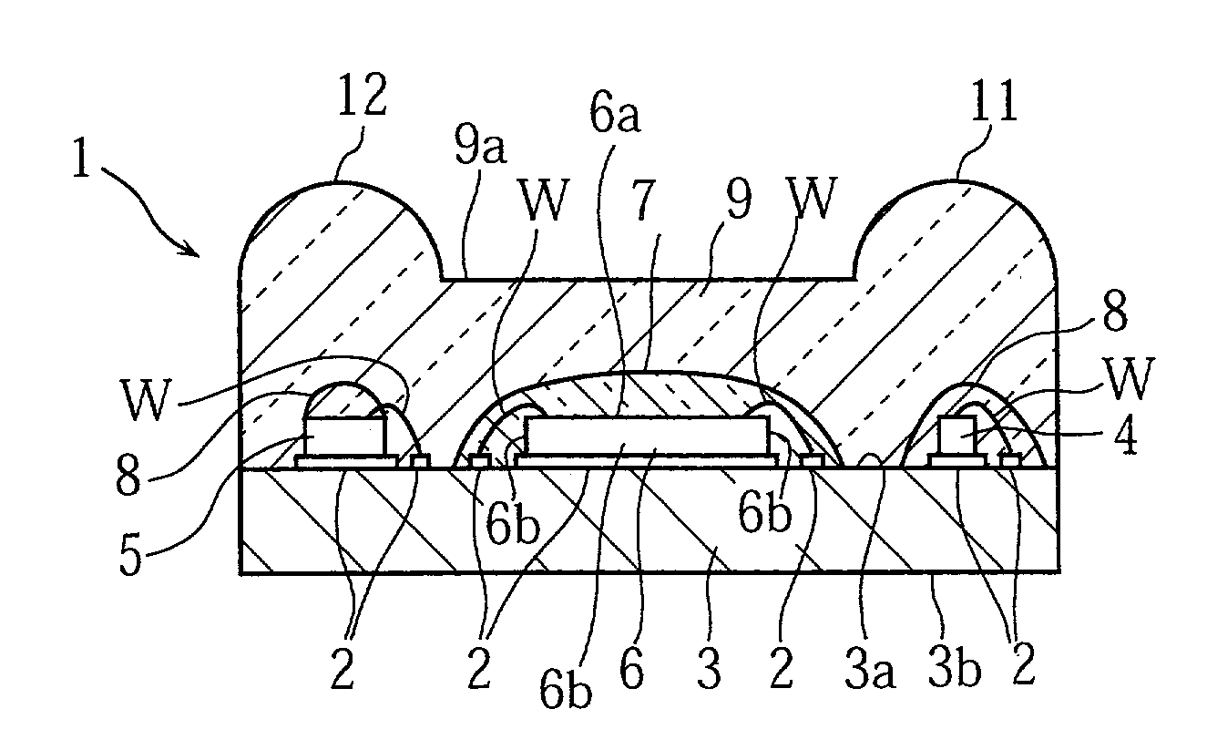
[0013]According to a first aspect of the present invention, there is provided an infrared data communication module comprising a substrate having a surface on which a light emitting element, a light receiving element, and an IC element are mounted. A resin package is formed on the substrate for integrally enclosing the light emitting element, the light receiving element and the IC element. A shield member is formed within the resin package for covering the IC element to protect the IC element against light-attributable noises.
[0017]With the above-described structure, the shield member prevents the light in the above-described wavelength range from reaching the IC element. Therefore, the malfunction of the IC element due to light-attributable noises can be prevented. Thus, the IC element operates stably to control the operation of the light emitting element and the light receiving element, thereby enhancing the reliability of the module. Further, the provision of the shield member eliminates the need for an expensive shield case, which reduces the cost for the parts of the module. Further, in the manufacturing process, the process step for attaching the shield case to the module can be eliminated, which contributes to the shortening of the manufacturing time and the reduction of the manufacturing cost.

Problems solved by technology

However, in using the module 1 as a part of such an electronic apparatus, the IC element 6 may be adversely affected by noises generated internally or externally of the apparatus.
Generally, however, such a circuit is not effective for avoiding the influences of light.
However, the provision of the shield case 28 increases the parts cost of the module 1.
Moreover, the process step of attaching a shield case 28 to a module 1 one by one increases the manufacturing cost.

Method used


Image

  • Infrared data communication module and method of making the same
  • Infrared data communication module and method of making the same
  • Infrared data communication module and method of making the same

Examples


Embodiment Construction

[0035]Preferred embodiments of the present invention will be described below in detail with reference to the accompanying drawings. In the following description, reference will be made again to FIG. 12 which has been used for describing the prior art module.

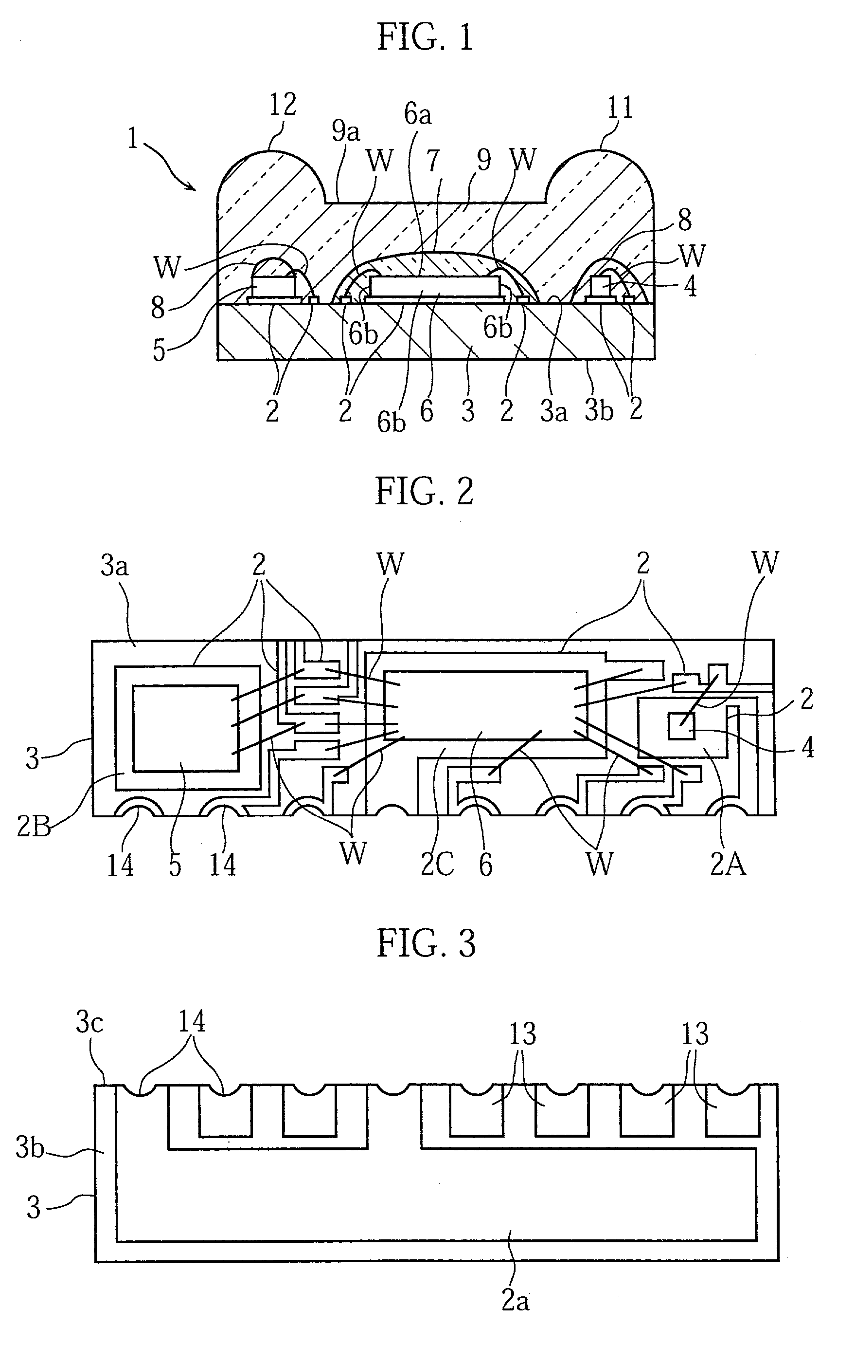
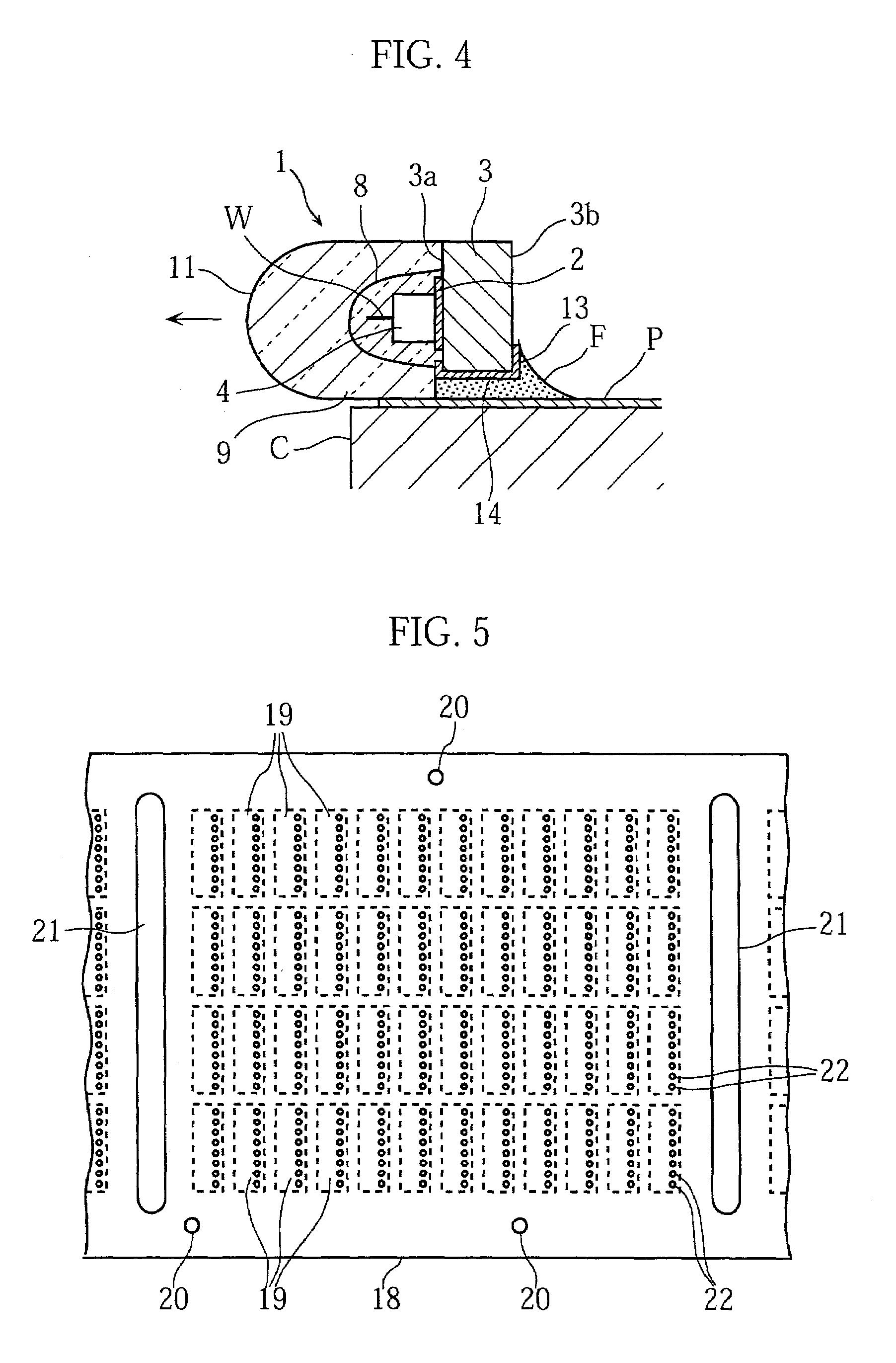
[0036]As shown in FIGS. 1 and 12, an infrared data communication module 1 (hereinafter, simply referred to as “module”) embodying the present invention includes a generally rectangular substrate 3 having an obverse surface 3a on which are mounted a light emitting element 4, a light receiving element 5 and an IC element 6. The module 1 also includes a shield member 7 for shielding the IC element 6, two protective members 8 for covering the light emitting element 4 and the light receiving element 5, and a molded resin package 9 for integrally sealing these elements from above the substrate 3.

[0037]The substrate 3 may be formed of glass fiber-reinforced epoxy resin for example. Specifically, as shown in FIG. 2, the substrate 3 has a...


PUM


Abstract

An infrared data communication module includes a substrate having a surface on which a light emitting element, a light receiving element, and an IC element are mounted. A resin package is formed on the substrate for integrally enclosing the light emitting element, the light receiving element and the IC element. A shield member is formed within the resin package for covering the IC element to prevent light-attributable noises from reaching the IC element.

Description

BACKGROUND OF THE INVENTION[0001]1. Field of the Invention:[0002]The present invention relates to an infrared data communication module used for performing infrared data communication by IrDA (Infrared Data Association) method. The present invention also relates to a method for making such an infrared data communication module.[0003]2. Description of the Related Art:[0004]Infrared data communication modules are conventionally utilized for performing infrared data communication based on the IrDA (Infrared Data Association) method between different apparatuses such as notebook-size personal computers or mobile phones or between such an apparatus and a peripheral device such as a printer. A prior art infrared data communication module (hereinafter simply referred to as “module”) has such a structure as shown in FIGS. 12 and 13. Specifically, the module 1 includes a substrate 3 having a surface 3a formed with a conductor pattern 2, a light emitting element 4, a light receiving element 5...

Claims


Application Information

Patent Timeline
IPC IPC(8): H04B10/00H01L23/29H01L23/31H01L25/16H01L31/02H01L33/48H01L33/50H01L33/56H01L33/58H01L33/62
CPCH01L25/167H01L33/486H01L33/62H01L2224/48091H01L2224/48227H01L2224/49171H01L2224/45144H01L2224/73265H01L2924/1815H01L2924/3025H01L2924/12041H01L2924/00014H01L2924/00
Inventor HORIO, TOMOHARU
Owner ROHM CO LTD
Learn More