Well packer for a pipe string and a method of leading a line past the well packer

a technology of well packer and pipe string, which is applied in the direction of well packer, well accessories, drilling accessories, etc., can solve the problems of increasing the risk of signal deterioration or potential pressure leakage, demanding and time-consuming continuous connection of such lengths of line, and entail several connectors along the control line. , to achieve the effect of improving and facilitating the leading of one or more control lines

Inactive Publication Date: 2007-09-04
RESLINK
View PDF7 Cites 63 Cited by
  • Summary
  • Abstract
  • Description
  • Claims
  • Application Information

AI Technical Summary

Benefits of technology

[0011]The object of the invention is to improve and facilitate the leading of one or more control lines past at least one well packer on the outside of a pipe string in connection with the assembly and running of this into a well. The invention also aims to avoid or reduce the above disadvantages of prior art.
[0020]When running the pipe string into the well, the outer packer ring will protect the control line(s) against direct contact with surrounding pipes or the borehole, so as to avoid any frictional damage to the line(s). Therefore, as a result of this packer design, the outer packer ring may be made from materials that have sufficient rigidity, shear strength and wear resistance to resist said friction during the run-in into the well, but which are also strong enough to resist compressive forces in the well after the packer has been set.

Problems solved by technology

Continuous connection of such lengths of line is demanding and time consuming and therefore also costly.
In addition, having several connectors along the control line entails a greater risk of signal deterioration or potential pressure leaks via these.
If the control line is electroconductive, several connectors could also lead to a greater risk of inflow of well fluids, which may have an adverse effect on the electrical circuit in the line.
However, such material properties will reduce the rigidity and shear strength of the sealing element, weakening the ability of the well packer to resist axial compressive forces in the well.
When a control line is arranged in the radially outmost surface of the well packer, thus projecting a maximum distance from the pipe string, it also has poor protection against frictional damage caused by possible contact with a enclosing pipe or a borehole during run-in into a well.
Similarly, said material in the peripheral layer of the sealing element may also easily sustain damage when running into the well.
It may however be difficult upon activation and expansion of such a discontinuous sealing element, to achieve an adequate pressure seal around the control line and between the adjoining surfaces of the individual insert components.

Method used


Image

  • Well packer for a pipe string and a method of leading a line past the well packer
  • Well packer for a pipe string and a method of leading a line past the well packer
  • Well packer for a pipe string and a method of leading a line past the well packer

Examples


Embodiment Construction

[0041]The appended figures are schematic and may be somewhat distorted with regard to the shape, relative dimensions and mutual positioning of the components. In the following, identical details in the figures will be indicated by the same reference number.

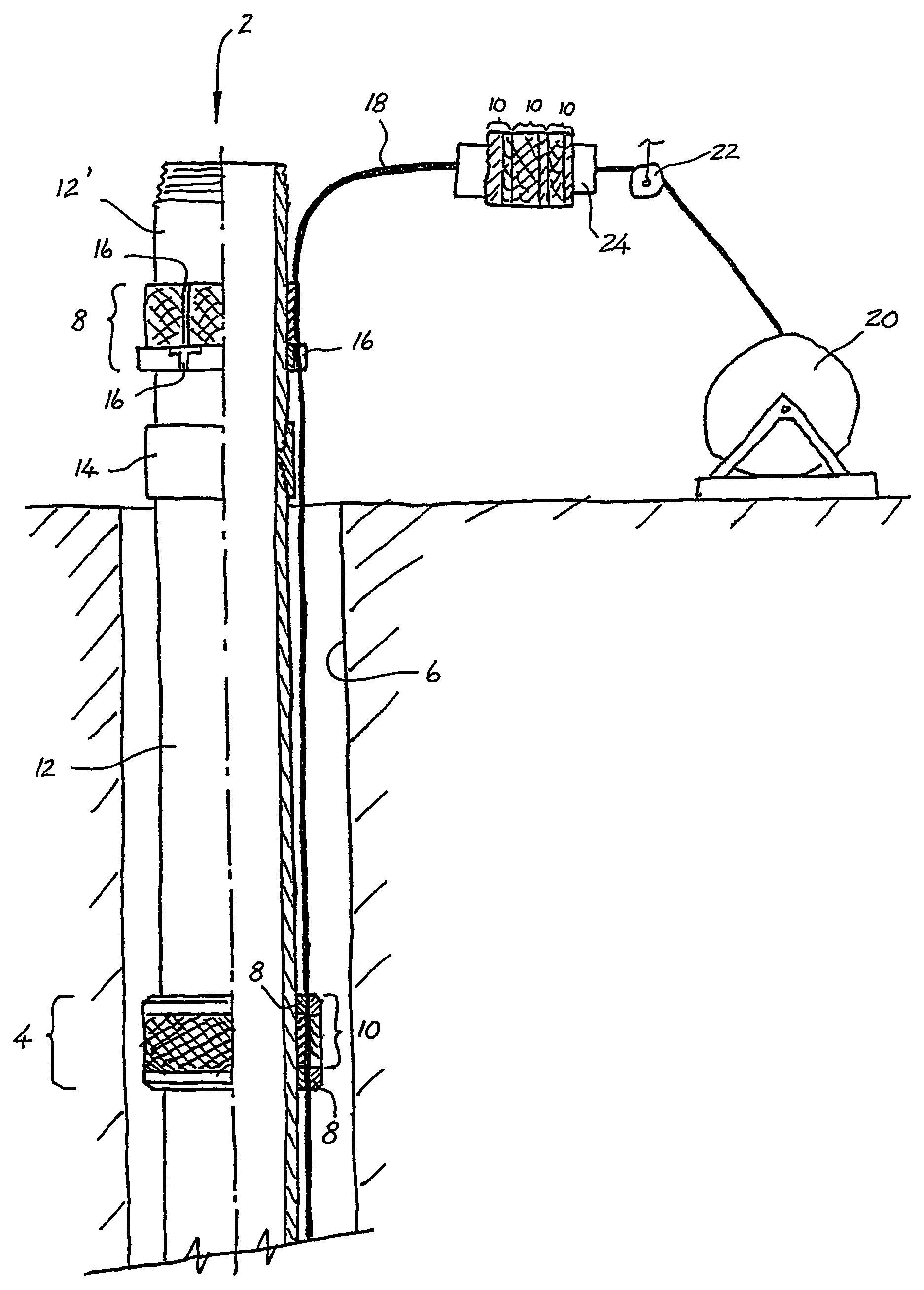
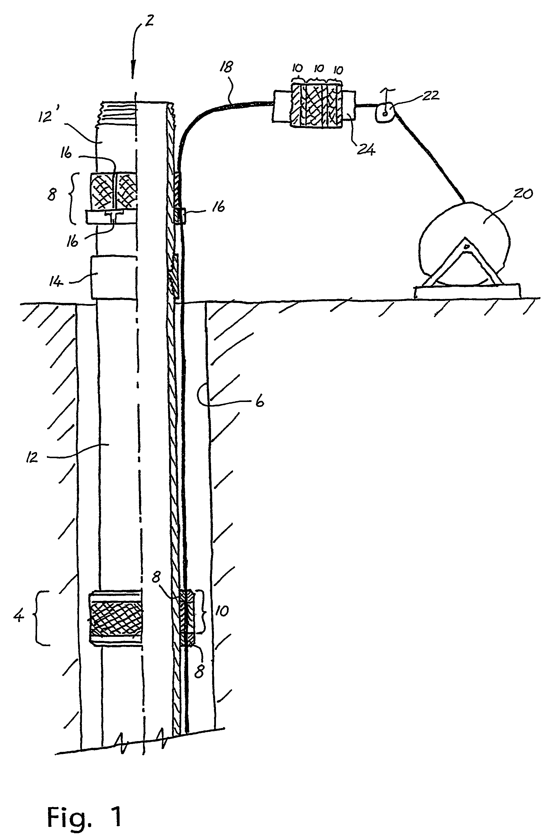
[0042]FIG. 1 shows a completion string 2, the outside of which is provided with well packers 4, and which is about to be screwed together and run into a well 6. According to the invention, each well packer 4 consists of a continuous inner packer ring 8 and a continuous outer packer ring 10. In the operating position, the outer packer ring 10 is placed outside the inner packer ring 8. Each packer ring 8, 10 is fitted with at least one flexible and expandable sealing element formed from e.g. a rubber material or an elastomer.

[0043]The completion string 2 consists of individual pipes 12 that are screwed together consecutively and lowered into the well 6. In the figure, the upper, free end of the string 2 is made up of a short pipe 12...


PUM


Abstract

The invention concerns an external well packer (4, 4′, 4″) for a pipe string (2), and also a method of leading at least one line (18) seamlessly past at least one packer (4, 4′, 4″) along the pipe string (2). What is characteristic of the packer (4, 4′, 4″) is that it consists of a continuous inner packer ring (8) and a separate and continuous outer packer ring (10), which in the operating position encloses the inner packer ring (8) in a pressure tight manner. The fitting surface of at least one of the packer rings (8, 10) is provided with at least one through-going line slot (16, 16′), which in the operating position encloses a line (18) in a pressure tight manner. This allows continuous lines (18) to be stretched out past several such packers (4, 4′, 4″).

Description

CROSS REFERENCE TO RELATED APPLICATION[0001]The present application is the U.S. national stage application of International Application PCT / NO2003 / 000343, filed Oct. 17, 2003, which international application was published on May 6, 2004 as International Publication WO 2004 / 038167. The International Application claims priority of Norwegian Patent Application 20025162, filed Oct. 25, 2002.BACKGROUND OF THE INVENTION[0002]The present invention regards an external packer for a pipe string in a well, e.g. a completion string, a production string or an injection string. The pipe string consists of several lengths of pipe joined successively as the string is run into the well. The invention also concerns a method of leading at least one line along the pipe string and seamlessly past one or more packers of the present type.[0003]Said line may be e.g. a hydraulic line, a fibre-optic line or another electroconductive line for transmission of actuating power or control signals to downhole well...

Claims


Application Information

Patent Timeline
Patent Type & Authority Patents(United States)
IPC IPC(8): E21B33/12E21B17/02E21B33/122
CPCE21B17/026E21B33/1208E21B33/122
Inventor DYBEVIK, ARTHURMOEN, TERJE
Owner RESLINK
Why Eureka
Try Eureka