Method of determining atmospheric refraction profile using two spatially separated light sources

a spatial separation and light source technology, applied in distance measurement, height/levelling measurement, instruments, etc., can solve the problems of affecting the precision of a determined extinction profile, difficult to know a concentration profile with a great deal of precision, and difficult to control/measure the motion of satellites or spacecrafts with sufficient precision

Active Publication Date: 2007-09-04
GLOBAL ATMOSPHERIC TECH & SCI INC
View PDF3 Cites 10 Cited by
  • Summary
  • Abstract
  • Description
  • Claims
  • Application Information

AI Technical Summary

Benefits of technology

[0008]Other objects and advantages of the present invention wi...

Problems solved by technology

The disadvantage of using the extinction technique is that one must know the concentration profiles of the absorbing gases in the atmosphere (e.g., CO2).
However, it is difficult to know a concentration profile with a great deal of precision since it can vary with altitude, atmospheric conditions, seasonal conditions, etc., thereby affecting the precision of a determ...

Method used


Image

  • Method of determining atmospheric refraction profile using two spatially separated light sources
  • Method of determining atmospheric refraction profile using two spatially separated light sources
  • Method of determining atmospheric refraction profile using two spatially separated light sources

Examples


Embodiment Construction

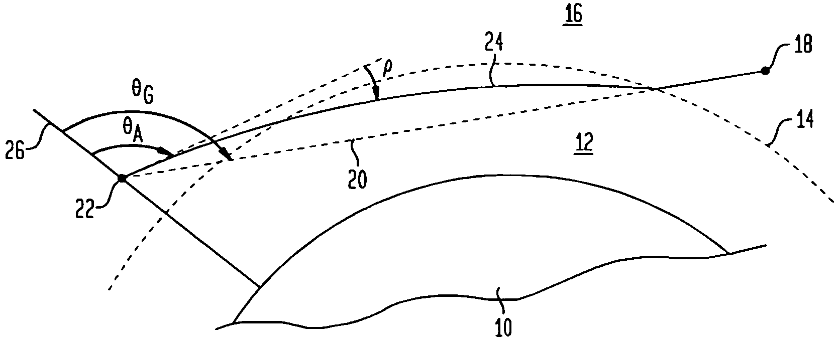
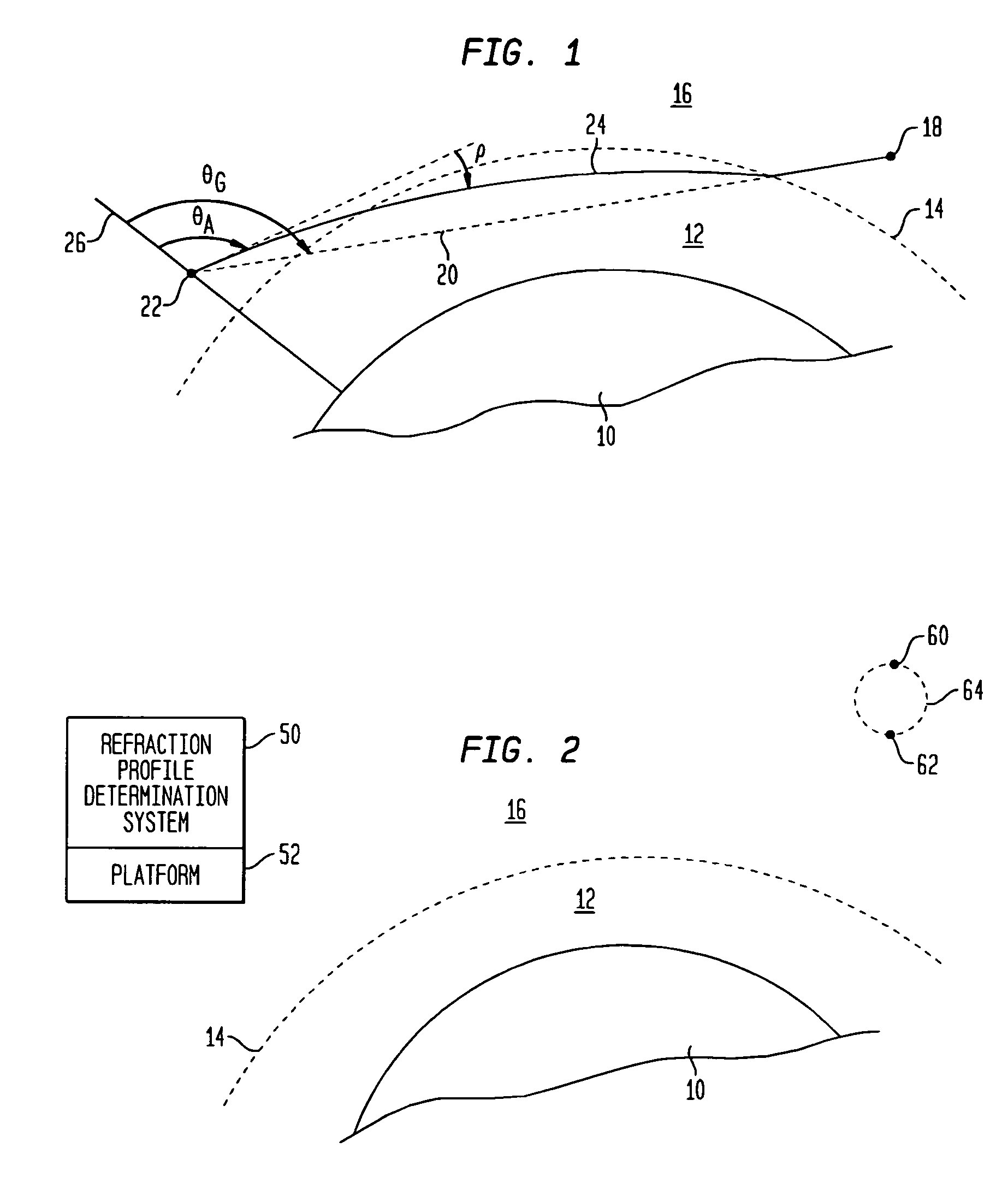
[0016]Prior to describing the method and system of the present invention, a brief description of refraction geometry associated with light passing through an atmosphere will be provided herein. By way of example, the earth and its refractive atmosphere will be discussed. However, it is to be understood that the same refraction geometry principles apply to any atmosphere and that the method and system of the present invention can be used to determine the refraction profile of any atmosphere, which, in turn, can be used to determine the atmosphere's temperature / pressure profile.

[0017]Referring now to the drawings, and more particularly to FIG. 1, the earth is referenced by numeral 10 and the earth's refractive atmosphere 12 lies between earth 10 and the dashed line referenced by numeral 14. As is known in the art, the earth's refractive atmosphere 12 is that portion of the earth's atmosphere that will cause a light beam to bend or refract as it passes therethrough. Accordingly, points...


PUM


Abstract

An atmospheric refraction profile is determined using an imaging system positioned at a location that is simultaneously within line-of-sight of two celestial light sources. A variety of active or passive methods can be employed to cause the line-of-sight to vertically traverse through a refractive portion of an atmosphere. Images of the two celestial light sources are captured as the line-of-sight vertically traverses through the refractive portion of the atmosphere. Each such image indicates an apparent distance between the two celestial light sources. The apparent distances are used to determine refraction angles.

Description

FIELD OF THE INVENTION[0001]The invention relates generally to atmospheric refraction measurements, and more particularly to a method and system for determining an atmospheric refraction profile that is not affected by sensor motion.BACKGROUND OF THE INVENTION[0002]Occultation sensing of an atmosphere (e.g., the earth's atmosphere) is a well-developed and highly useful technique. Briefly, occultation sensing involves passing light through an atmosphere's limb and then viewing the light at a remotely-located sensor (e.g., a sensor in orbit in or beyond the atmosphere). The sensed light is analyzed to determine the properties of the occulting atmosphere.[0003]The output of occultation sensors can be used to infer an atmosphere's temperature profile as a function of altitude based on either an extinction or refraction profile of the light passed through the atmosphere's limb. In both techniques, light from a single source (e.g., a star) is sensed after that light passes through the atm...

Claims


Application Information

Patent Timeline
IPC IPC(8): G01C3/00
CPCG01C11/06
Inventor GORDLEY, LARRY L.
Owner GLOBAL ATMOSPHERIC TECH & SCI INC
Why Eureka
Try Eureka