Methods and devices for creating electrical block at specific sites in cardiac tissue with targeted tissue ablation

a targeted tissue and electrical block technology, applied in the field of electrophysiology, can solve the problems of difficult positioning of the device accurately, the depth of the ablation may extend beyond the targeted, and the method has become characterized with uncertainty as to whether the appropriate amount of ablation is appropriate, so as to achieve precise ablation device and technique, easy to create linear ablation scars, and achieve targeted ablation damage to tissue.

Inactive Publication Date: 2007-09-04
SYNTACH AG
View PDF99 Cites 93 Cited by
  • Summary
  • Abstract
  • Description
  • Claims
  • Application Information

AI Technical Summary

Benefits of technology

[0013]It is a further object of the present invention to provide a more precise ablation device and technique to create electrical block.
[0014]It is yet a further object of the present invention to provide a device which creates focused ablation damage to tissue.
[0015]It is yet a further object of the present invention to provide a device which allows a user to easily create linear ablation scars.
[0016]It is a further object of the present invention to provide a device that more reliably creates electrical block in cardiac tissue.
[0017]In one embodiment, the present invention attempts to achieve these objects by providing a bipolar ablation device with multiple needle electrodes that penetrate a desired target tissue. These electrodes may be arranged in a variety of therapeutically effective arrangements, such as a comb-like shape, a multi-needle wheel, or an expanding bow design. By contacting and preferably penetrating the cardiac tissue with bipolar electrodes, a user can more precisely create ablation-induced scarring and thus electrical block at desired target locations without causing unwanted damage and related complications.

Problems solved by technology

Since the atria are relatively large chambers and are moving with the beating of the heart, it is difficult, however, to position these devices accurately.
These methods have proven to be not only very time consuming but also have become characterized with uncertainty as to whether the appropriate amount of ablation has been performed or if the desired target location is being ablated.
For example, the resulting depth of the ablation may extend beyond the targeted tissue and injure adjacent tissue such as the esophagus, the trachea or the bronchial tubes.
Other possible adverse outcomes of not successfully ablating the desired target site or ablating too much or too little include: not successfully blocking the electrical pathway, disrupting the wrong pathway or creating stenosis in a vessel such as a pulmonary vein.
Of these adverse outcomes, creating a stenosis is a particularly serious complication.
Stenoses as a result of this type of energy ablation in the pulmonary veins has been reported in a small percentage of cases, however it is uncertain if these stenoses are caused more by excessive ablation, missing the appropriate target site or are an inherent risk for this type of treatment in the pulmonary veins.
The motion of the heart makes it very difficult to accurately control the position of the device in this way.
These concepts address some of the problems with locating the ablation elements relative to the pulmonary vein but are potentially limited in that they presume a round pulmonary vein and are geared towards making a circumferential ablation around the veins.
These systems are not optimally suited for creating focal ablations of discrete points or for making linear lesions other than the circumferential lesions around the device location.
While these approaches can address some of the limitations discussed above, they require a much more invasive access.

Method used


Image

  • Methods and devices for creating electrical block at specific sites in cardiac tissue with targeted tissue ablation
  • Methods and devices for creating electrical block at specific sites in cardiac tissue with targeted tissue ablation
  • Methods and devices for creating electrical block at specific sites in cardiac tissue with targeted tissue ablation

Examples


Embodiment Construction

[0032]As previously described, there are a number of mechanisms used to create electrical block acutely. Some of these mechanisms involve the use of energy delivery such as RF or microwave radiation to ablate a target tissue. In these instances, energy is typically applied to either the endocardial or epicardial surface using mono-polar devices.

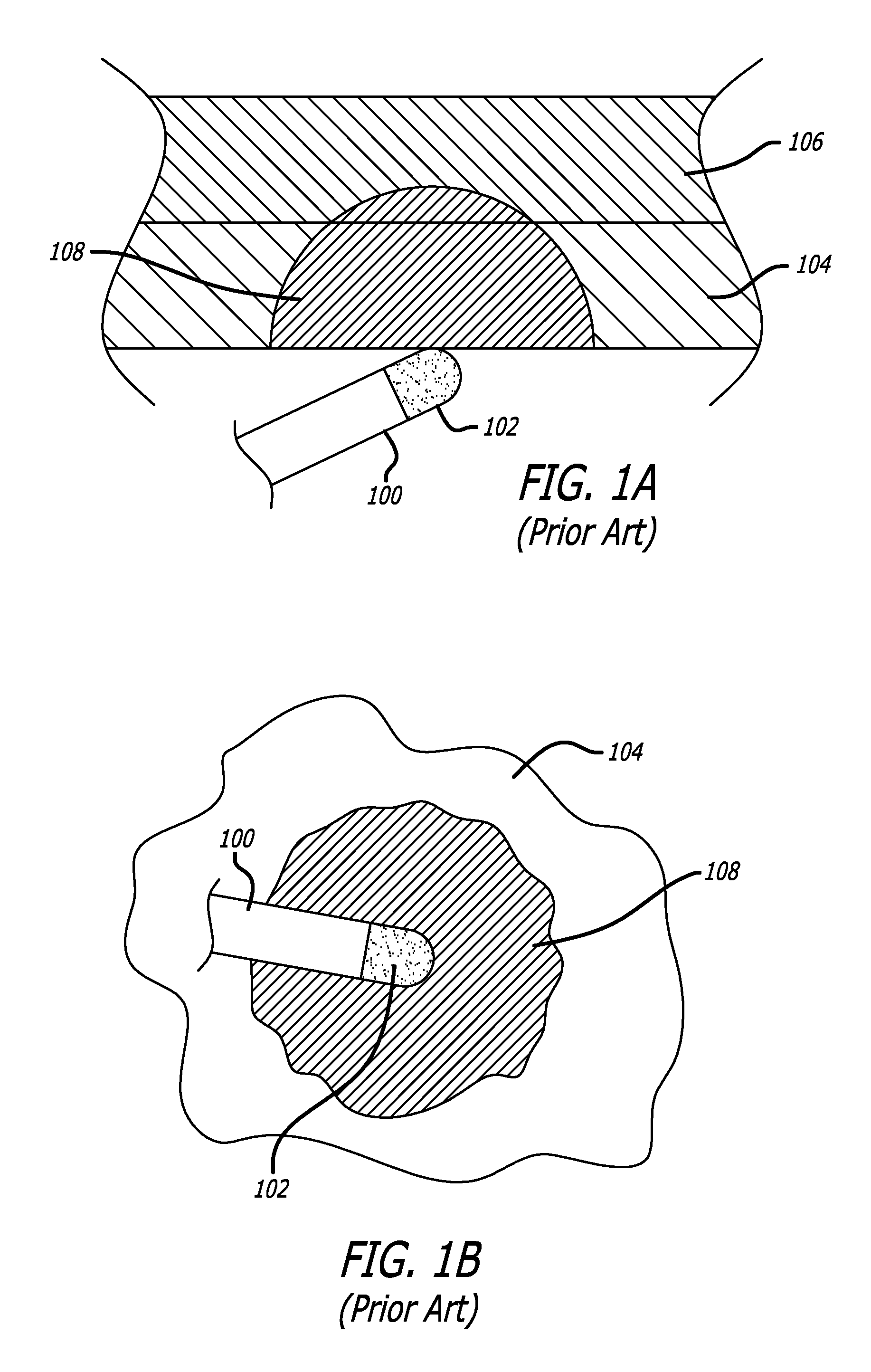
[0033]More specifically, the ablation energy is delivered through a small surface area ablation tip and transmitted through the tissue to a large area ground plate in contact with the body at a far removed site. The result is a concentration of the ablative current immediately around the ablation tip that rapidly decreases as the current travels further into the tissue, away from the ablation tip.

[0034]FIGS. 1A and 1B illustrate this concept, depicting a mono-polar ablation device 100 with an ablation tip 102 contacting the tissue wall 104 of tissue 106. In most practices, it is believed that it is necessary for the lines of burns to be fully...


PUM


Abstract

In one embodiment, the present invention provides a bipolar ablation device with multiple needle electrodes that penetrate a desired target tissue. These electrodes may be arranged in a variety of therapeutically effective arrangements, such as a comb-like shape, a multi-needle wheel, or an expanding bow design. By contacting and preferably penetrating the cardiac tissue with bipolar electrodes, a user can more precisely create ablation-induced scarring and thus electrical block at desired target locations without causing unwanted damage and related complications.

Description

RELATED APPLICATIONS[0001]This application claims priority to U.S. Provisional Application Ser. No. 60 / 514,428 filed Oct. 24, 2003 entitled Methods And Devices For Creating Electrical Block At Specific Sites In Cardiac Tissue With Targeted Tissue Ablation and is hereby incorporated by reference.BACKGROUND OF THE INVENTION[0002]In the field of electrophysiology, there are numerous methods that seek to create blocks of specific electrical pathways for the treatment of atrial arrhythmias. These methods primarily rely on applying energy to the tissue to ablate the tissue and thereby block a pathway for electrical conduction. These techniques are used most often in the left or right atriums and can be used to create electrical block either at discrete sites or along linear paths. Examples of such techniques can be seen in prior art U.S. Pat. Nos. 6,237,605; 6,314,962; 6,527,769, 6,502,576 all of which are incorporated herein by reference.[0003]In a usage that is increasing in popularity,...

Claims


Application Information

Patent Timeline
Patent Type & Authority Patents(United States)
IPC IPC(8): A61B18/18A61N1/00A61B18/14A61N
CPCA61B18/1477A61B18/1492A61B2018/00214A61B2018/00898
Inventor CORNELIUS, RICHARDSWANSON, WILLIAM
Owner SYNTACH AG
Why Eureka
Try Eureka