A heart pulse multipolar ablation catheter

An ablation catheter and pulse technology, which is applied in the field of medical devices, can solve the problems of long operation time and large tissue cell damage, and achieve the effect of shortening operation time, reducing damage, and improving ablation efficiency

Active Publication Date: 2021-04-09
SICHUAN JINJIANG ELECTRONICS SCI & TECH CO LTD
View PDF7 Cites 0 Cited by
  • Summary
  • Abstract
  • Description
  • Claims
  • Application Information

AI Technical Summary

Problems solved by technology

[0006] The purpose of the present invention is to provide a heart pulse multipolar ablation catheter to safely, efficiently and accurately apply high-voltage pulse energy to large area of ​​target tissue

Method used


Image

  • A heart pulse multipolar ablation catheter
  • A heart pulse multipolar ablation catheter
  • A heart pulse multipolar ablation catheter

Examples


Embodiment 1

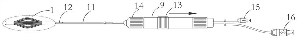
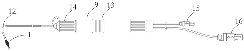
[0045] Such as figure 1 As shown, a cardiac pulse multipolar ablation catheter according to the present invention consists of an electrode assembly 1, a tube body and a handle 9, the tube body includes a support tube 11 and a controllable bend tube 12, and the electrode assembly 1 is connected to the The end of the controllable bend tube 12, the handle 9 is connected to the proximal end of the support tube 11. Such as figure 2 As shown, the controllable bend 12 is a tube body braided by polyurethane, and the handle 9 can control the bending degree of the controllable bend 12 through the adjustment knob 14; wherein, the inside of the controllable bend 12 is a multi-lumen structure . The support tube 11 is a braided tube body of PEBAX and polyurethane, with an outer diameter of 7.5-12F, and is used to support the controllable bend tube 12 and the connecting handle 9 . The handle 9 also includes a connector A15 and a connector B16, the connector A15 is used to transmit the co...

Embodiment 2

[0051] The difference between this embodiment and Embodiment 1 is that a ring electrode group is added in this embodiment. Such as Figure 9 , Figure 10 As shown, in order to make the shape acquisition and display of the electrode 3 more accurate, the present invention further sets a distal ring electrode 19 and a proximal ring electrode 20 on the distal end and the proximal end of the electrode assembly 1 respectively. The electrode 19 and the proximal ring electrode 20 are respectively arranged at positions close to the magnetic positioning sensor, and the relative position of the distal ring electrode 19 and the distal magnetic positioning sensor 17 and the relative position between the proximal ring electrode 20 and the The relative positions of the proximal magnetic positioning sensors 18 are the same. Since only using the electric field for positioning has low accuracy and can only calculate the relative positional relationship, the present invention can accurately de...

Embodiment 3

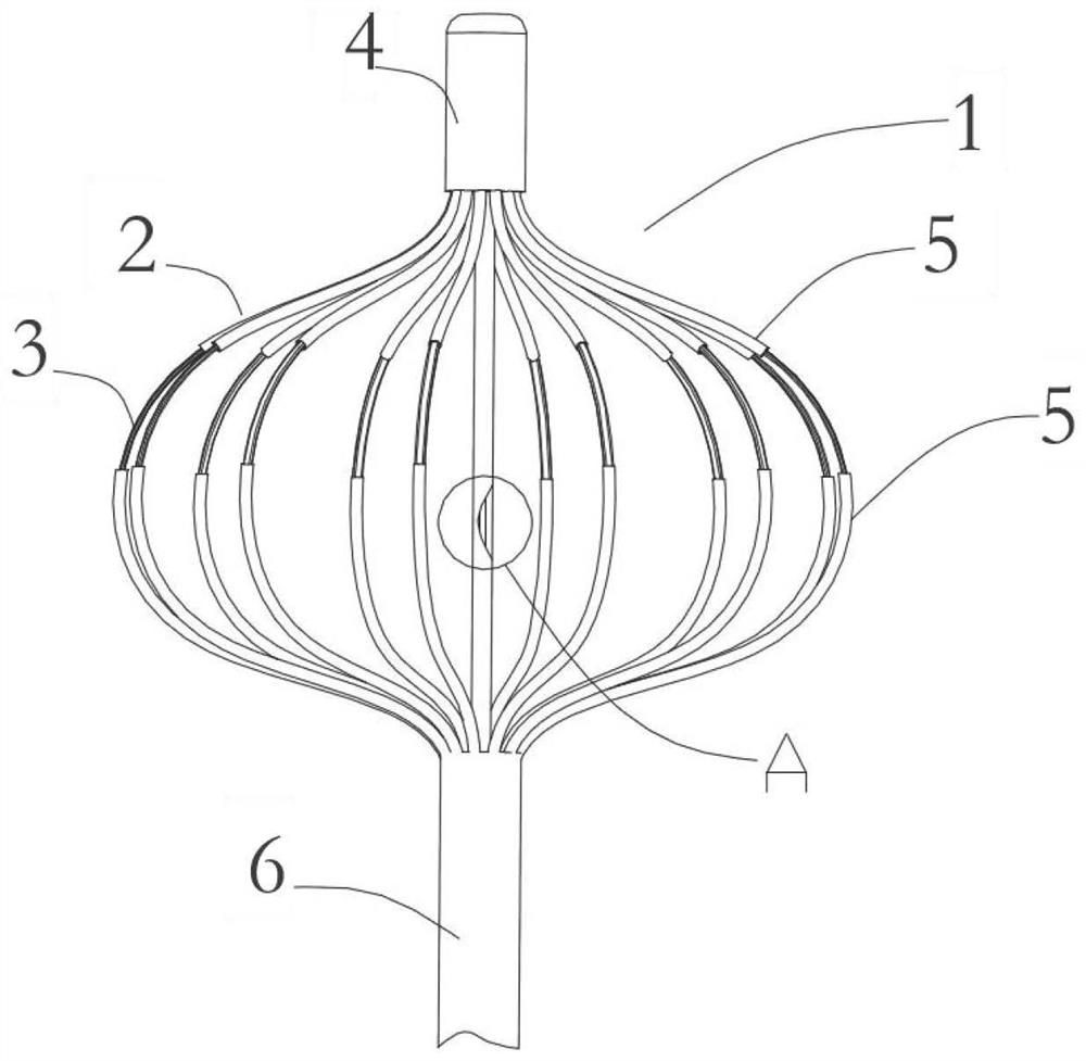
[0056] The difference between this embodiment and the above-mentioned embodiments is that the electrode 3 of this embodiment is replaced by a ring electrode. Such as Figure 11 As shown, the electrode 3 adopts a ring electrode and is arranged on the electrode arm 2. At least one electrode 3 is arranged on each electrode arm 2, and the position of the electrode 3 is above the equator line B. If each electrode arm is provided with two electrodes 3, then the first Two electrodes 3 are arranged below the equator line B.


PUM


Abstract

The present invention relates to the field of medical devices, in particular to a cardiac pulse multipolar ablation catheter, comprising an electrode assembly, a tube body and a handle, the electrode assembly is connected to the end of the tube body, and the handle is connected to the end of the tube body Proximity; the electrode assembly includes an even number of electrode arms uniformly arranged in the ring, and electrodes are arranged on the electrode arms, and each group of adjacent two electrodes generates pulses with the same pulse width and equal field strength but polarity. The opposite train of high-voltage energy bursts acts on the heart muscle cells. The present invention constitutes a multi-pole array through the electrodes arranged on a plurality of electrode arms, and then forms an annular ablation zone, which can more effectively ablate tissue cells, greatly shorten operation time, and greatly improve ablation efficiency; Energy pulse train ablation can selectively ablate target tissue, reduce damage to tissue cells, and reduce the incidence of complications.

Description

technical field [0001] The invention relates to the field of medical devices, in particular to a cardiac pulse multipolar ablation catheter. Background technique [0002] Radiofrequency (RF) ablation and cryoablation are two commonly used clinical methods for the treatment of arrhythmias such as atrial fibrillation. The success of ablation depends primarily on the quality and adequacy of the lesions created during the procedure. The injury must be sufficient to destroy the arrhythmogenic tissue or to sufficiently disrupt or isolate abnormal electrical conduction within the myocardial tissue. But excessive ablation will have an impact on surrounding healthy tissue and nerve tissue. Radiofrequency ablation can reach all cardiac anatomical locations, and is suitable for arrhythmias including atrial fibrillation, atrial flutter, atrial tachycardia, premature ventricular, and ventricular tachycardia originating from pulmonary veins or non-pulmonary veins. The level requirement...

Claims


Application Information

Patent Timeline
Patent Type & Authority Patents(China)
IPC IPC(8): A61B18/12A61B18/14A61B34/20
CPCA61B18/12A61B18/1492A61B2018/00059A61B2018/00351A61B2018/00595A61B2018/1405A61B2018/1407A61B2018/1467A61B34/20A61B2034/2051
Inventor 朱晓林曾红兵邹波
Owner SICHUAN JINJIANG ELECTRONICS SCI & TECH CO LTD
Why Eureka
Try Eureka