
Foot scrubbing apparatus

Inactive Publication Date: 2007-09-11
MEZYED YOSRY N
View PDF10 Cites 11 Cited by
  • Summary
  • Abstract
  • Description
  • Claims
  • Application Information

AI Technical Summary

Benefits of technology

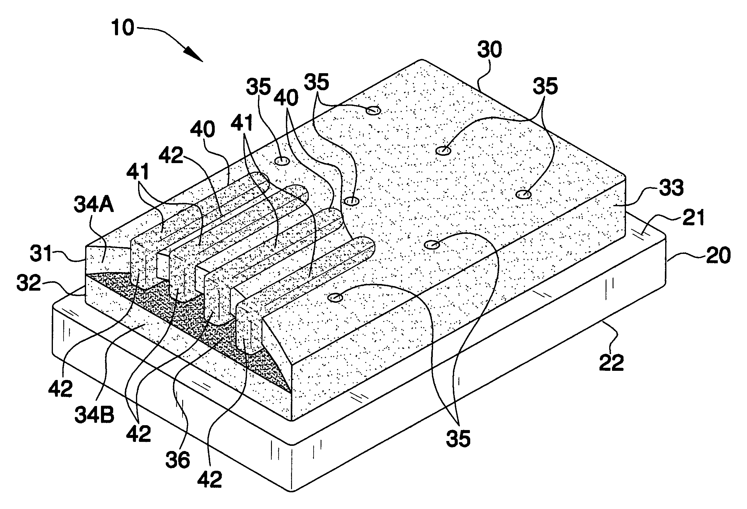
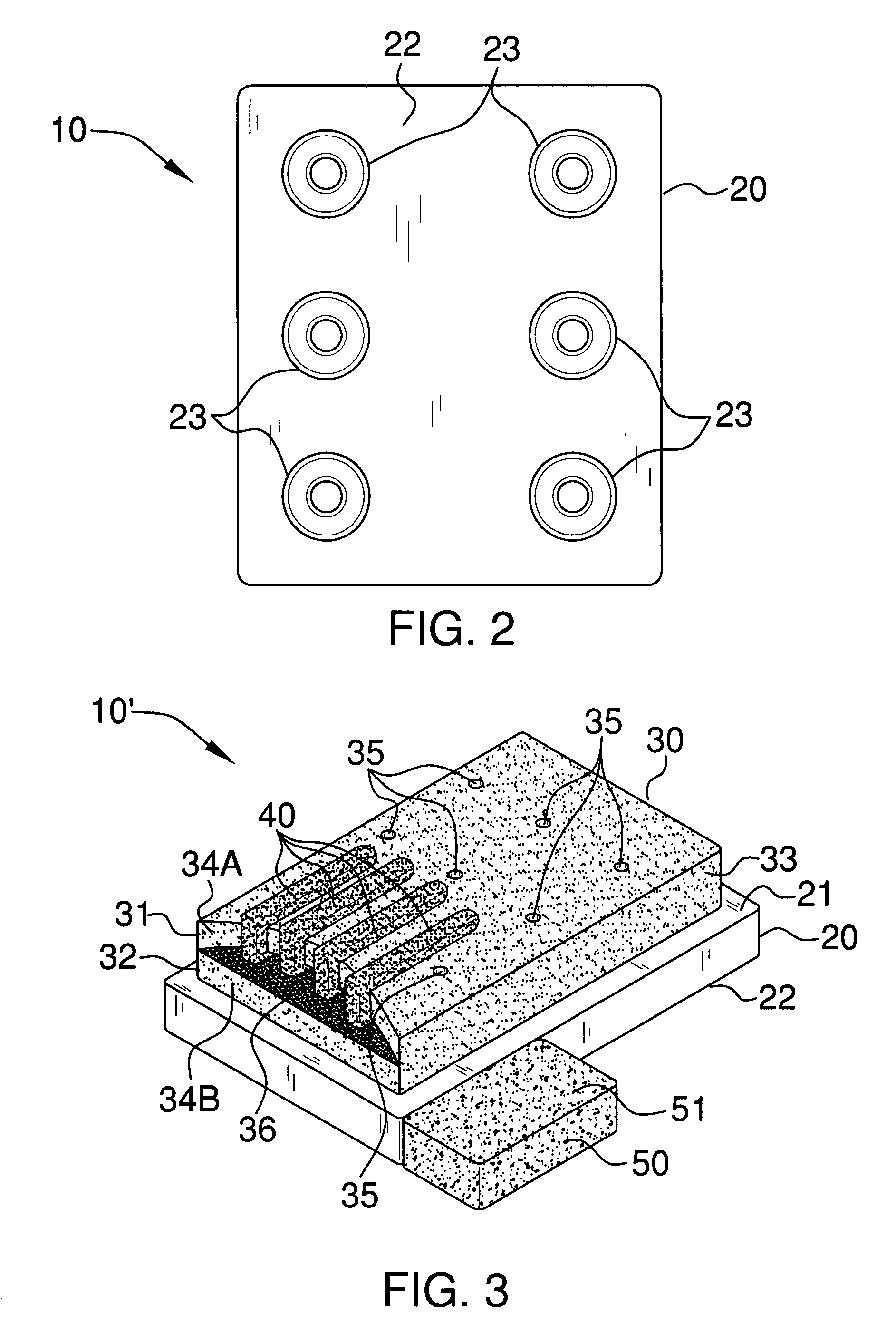
[0013]A plurality of suction cups are directly and permanently secured to the bottom surface of the base member. Such suction cups are detachably engageable directly to a moist support surface so that the apparatus can effectively be maintained at a static position without requiring the user to bend over and hold the apparatus in place during operating conditions.
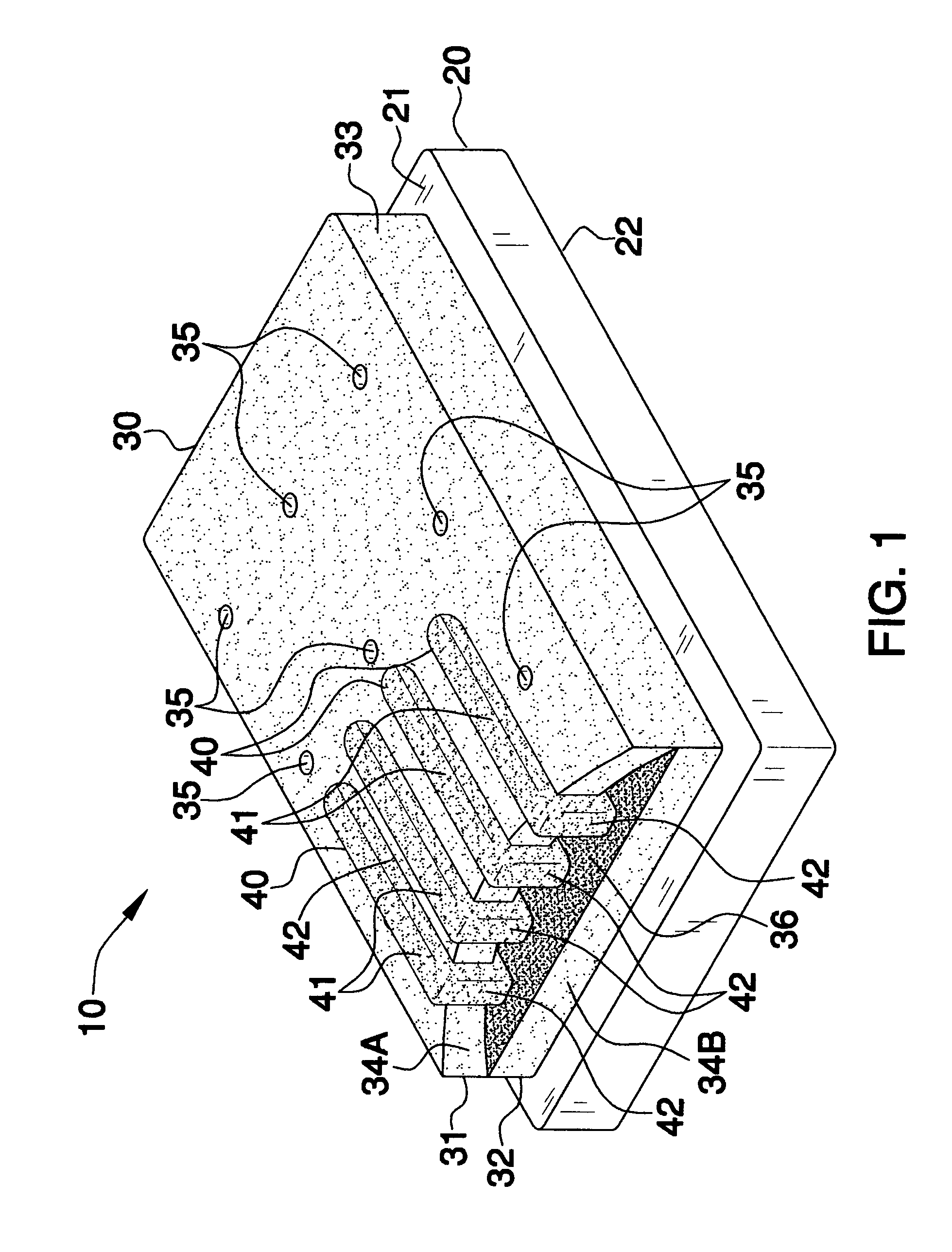
[0014]A primary sponge member includes detachably engageable top and bottom layers that define a cavity therebetween for effectively receiving a user's foot along a longitudinal axis of the apparatus. Such a cavity is sized and shaped such that the user's entire foot can advantageously be slidably inserted between the top and bottom layers while maintaining continuous surface area contact therewith and cleaning an entire surface area of the user's foot. The primary sponge member preferably has monolithically formed side walls for effectively preventing the top and bottom layers from becoming permanently disengaged from each other.
[0015]The top and bottom layers have vertically offset front edge portions for conveniently assisting the user to insert the user's foot into the cavity during repeated use. The front edge of the top layer may be distally recessed from the front edge of the bottom layer for conveniently assisting the user to cleanse a heel portion of the user's foot during operating conditions. The primary sponge member may be provided with a plurality of apertures spaced along the top layer that pass downwardly to the cavity for conveniently impregnating a cleansing agent directly through the top layer and onto the bottom layer of the primary sponge member.
[0016]A plurality of secondary sponge members are directly conjoined to the top layer of the primary sponge member and longitudinally extend along a partial length of the top layer. Such secondary sponge members are sized and shaped such that a user's toes can effectively be selectively nested between the secondary sponge members during a linear and longitudinal sliding movement along the top layer. The secondary sponge members have surface textures which are coarser than a surface texture of the primary sponge member so that the user can effectively clean tough skin surfaces adjacent to the user's toes. The bottom layer preferably includes an arcuate shaped top portion that is coarser than a remaining portion of the primary sponge material. Such a top portion extends proximally from the front edge of the top layer.
[0018]In an alternate embodiment, a pumice stone may be directly connected to the base member and provided with a top surface laterally offset subjacent the top layer so that the user can advantageously quickly and effectively rub a bottom surface of the user's foot along the pumice stone without directly contacting the primary and secondary sponge members.

Problems solved by technology

It is well known that difficulty and potential danger are involved with the manual washing of a person's own feet while taking a shower.
Not only is it a chore to bend over to accomplish manual foot washing, but the act of doing so involves a balancing act on the other foot which is, at best, less than safe, and for some, potentially very dangerous.
In spite of this, a person must nonetheless see to the proper hygiene of his or her feet, as they are frequently subject to becoming dirty and odoriferous, which may lead to fungal growths and other foot ailments that are costly and time consuming to cure.
While brushes can adequately perform a cleansing task on many surfaces, brushes tend to be harsh when applied to soft skin, such as that found on the top of a person's feet.
Further, soap may not be well retained over a long term with respect to the bristles, especially in a shower environment of use.
Other foot scrubbing devices are adequate in their function but not in their design.
These devices are complicated in design, thus raising the cost of production, and subsequently, the cost to the consumer, above an acceptable level.

Method used


Image

  • Foot scrubbing apparatus
  • Foot scrubbing apparatus
  • Foot scrubbing apparatus

Examples


Embodiment Construction

[0025]The present invention will now be described more fully hereinafter with reference to the accompanying drawings, in which preferred embodiments of the invention are shown. This invention may, however, be embodied in many different forms and should not be construed as limited to the embodiments set forth herein. Rather, these embodiments are provided so that this application will be thorough and complete, and will fully convey the true scope of the invention to those skilled in the art. Like numbers refer to like elements throughout the figures and prime numbers refers to alternate embodiments of such elements.

[0026]The apparatus of this invention is referred to generally in FIGS. 1-3 by the reference numeral 10 and is intended to provide a foot scrubbing apparatus. It should be understood that the apparatus 10 may be used to scrub many different appendages of both humans and animals, and should not be limited in use to only scrubbing one's feet in the shower.

[0027]Referring ini...


PUM


Abstract

A foot-scrubbing apparatus includes a non-porous and rigid base member that has planar top and bottom surfaces and suction cups permanently secured to the bottom surface. A primary sponge includes detachably engageable top and bottom layers defining a cavity therebetween for slidably receiving a user's entire foot. The top and bottom layers have vertically offset front edge portions for assisting the user to insert their foot into the cavity. A plurality of secondary sponges are directly conjoined to the top layer of the primary sponge and extend longitudinally therealong. The secondary sponges are sized and shaped such that a user's toes can be selectively nested between the secondary sponges. The secondary sponges have coarser surface textures than the primary sponge surface texture so that the user can clean tough skin surfaces adjacent to their toes.

Description

CROSS REFERENCE TO RELATED APPLICATIONS[0001]Not Applicable.STATEMENT REGARDING FEDERALLY SPONSORED RESEARCH OR DEVELOPMENT[0002]Not Applicable.REFERENCE TO A MICROFICHE APPENDIX[0003]Not Applicable.BACKGROUND OF THE INVENTION[0004]1. Technical Field[0005]This invention relates to foot scrubbing apparatuses and, more particularly, to a foot scrubbing apparatus for promoting personal hygiene.[0006]2. Prior Art[0007]It is well known that difficulty and potential danger are involved with the manual washing of a person's own feet while taking a shower. Not only is it a chore to bend over to accomplish manual foot washing, but the act of doing so involves a balancing act on the other foot which is, at best, less than safe, and for some, potentially very dangerous. This is especially true for elderly individuals and those with debilitating back pain or other physical disabilities that prevent excessive bending of their backs. In spite of this, a person must nonetheless see to the proper h...

Claims


Application Information

Patent Timeline
IPC IPC(8): A47K7/03
CPCA47K7/026
Inventor MEZYED, YOSRY N.
Owner MEZYED YOSRY N
Learn More