
Portable beverage dispensing system

a beverage dispensing and portable technology, applied in the direction of liquid dispensing, liquid transferring device, packaging, etc., can solve the problems of difficult or impossible transportation, time-consuming process, passengers often being unable to obtain beverages,

Inactive Publication Date: 2007-09-11
INNOVATIVE SYST & CYLINDERS
View PDF20 Cites 46 Cited by
  • Summary
  • Abstract
  • Description
  • Claims
  • Application Information

AI Technical Summary

Benefits of technology

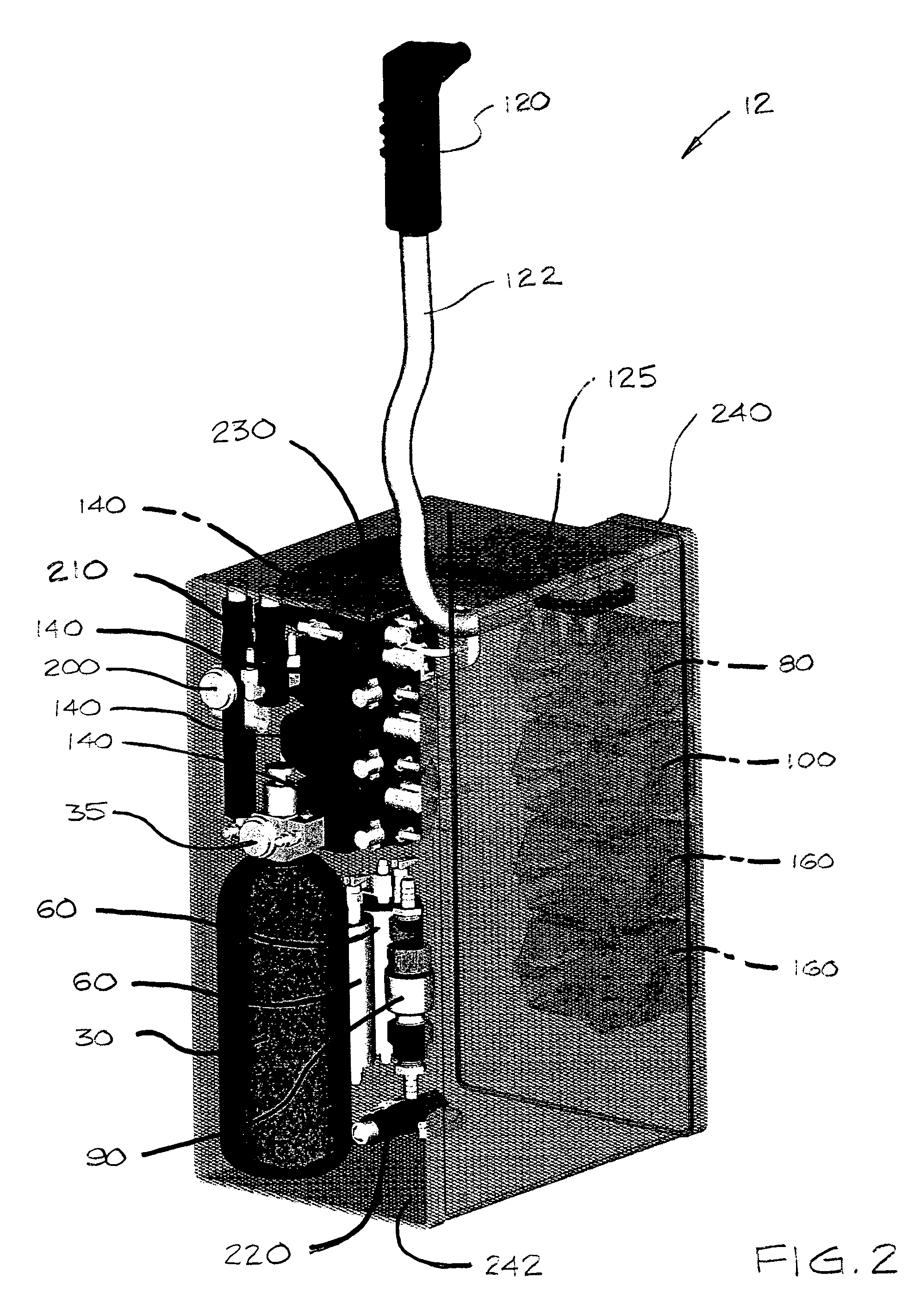
[0009]A high pressure gas cylinder for a portable beverage dispensing system includes a neck having a throat. A piercable membrane seals the throat of the cylinder. The term “high pressure gas cylinder” as used herein refers to cylinder that is capable of safely storing compressed gas at a pressure of at least about 1800 psi.

Problems solved by technology

This process is time-consuming, and can be difficult or impossible under turbulent flight conditions.
On short flights, at least some passengers often are unable to obtain a beverage due to the time required to dispense canned beverages to previously served passengers.
In addition, the cost per serving of canned beverages is considerably higher than the cost per serving cost post-mixed carbonated beverages.
Serving pre-packaged beverages also generates considerable waste such as empty beverage cans that must be handled, temporarily stored, and discarded.
In addition, pre-packaged carbonated beverages have a limited shelf life.
The challenges associated with producing compact and portable post-mix beverage dispensing systems are numerous.
In addition, such systems must be sufficiently compact to permit their use in limited spaces such as the narrow confines of airplanes.
Others have attempted to produce compact and portable post-mix beverage dispensing systems with limited success.
Unfortunately, such low-pressure motorless carbonators produce soda having only about 2.5 percent carbonation, which is well below a commercially acceptable level of carbonation and / or product standards dictated by makers of Coke ® and Pepsi®.
Unfortunately, these systems also do not provide a highly portable and compact beverage dispensing system that produces soda that consistently meets commercially acceptable levels of carbonation and complies with applicable federal safety regulations for use on commercial aircraft.

Method used


Image

  • Portable beverage dispensing system
  • Portable beverage dispensing system
  • Portable beverage dispensing system

Examples


Embodiment Construction

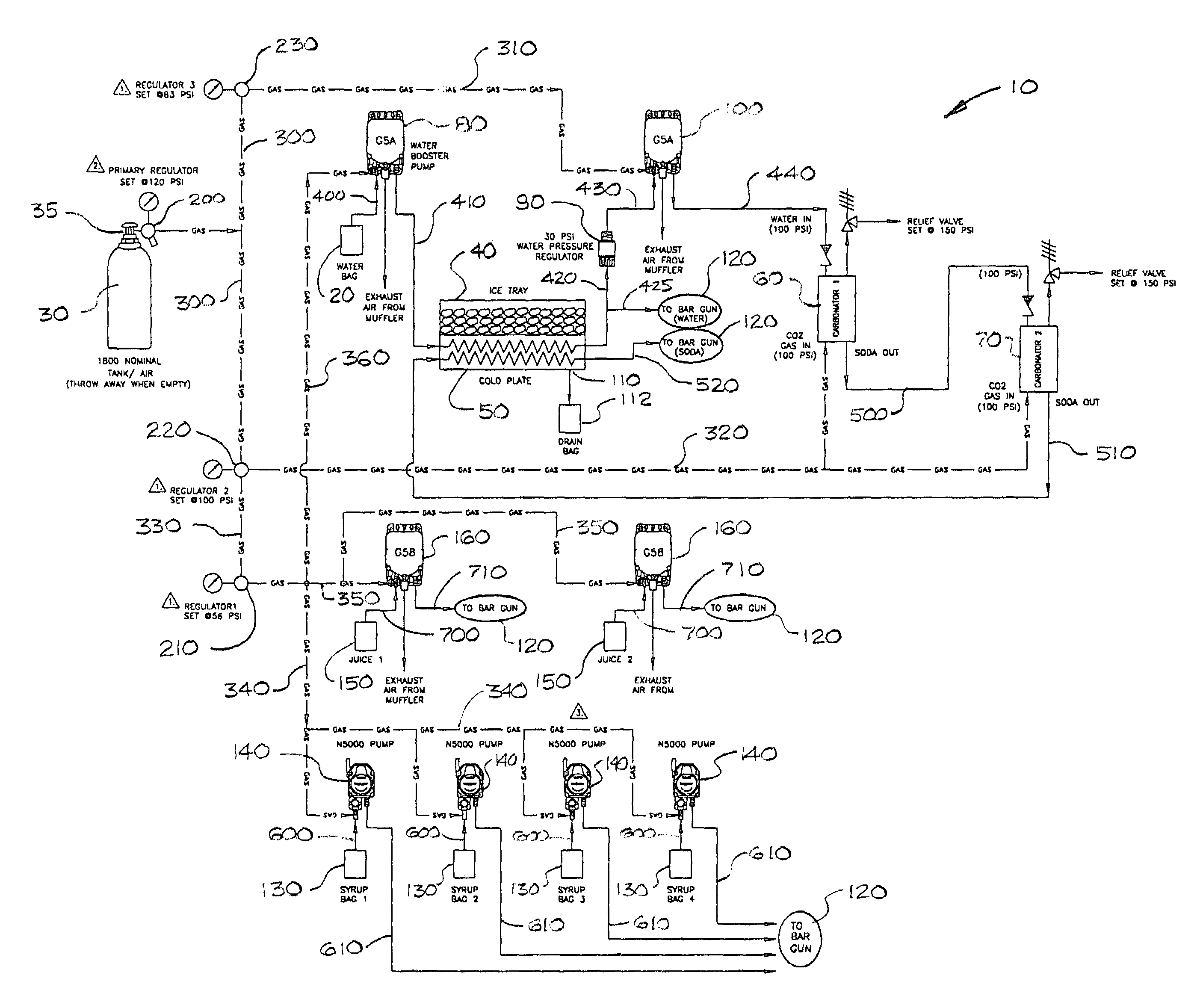
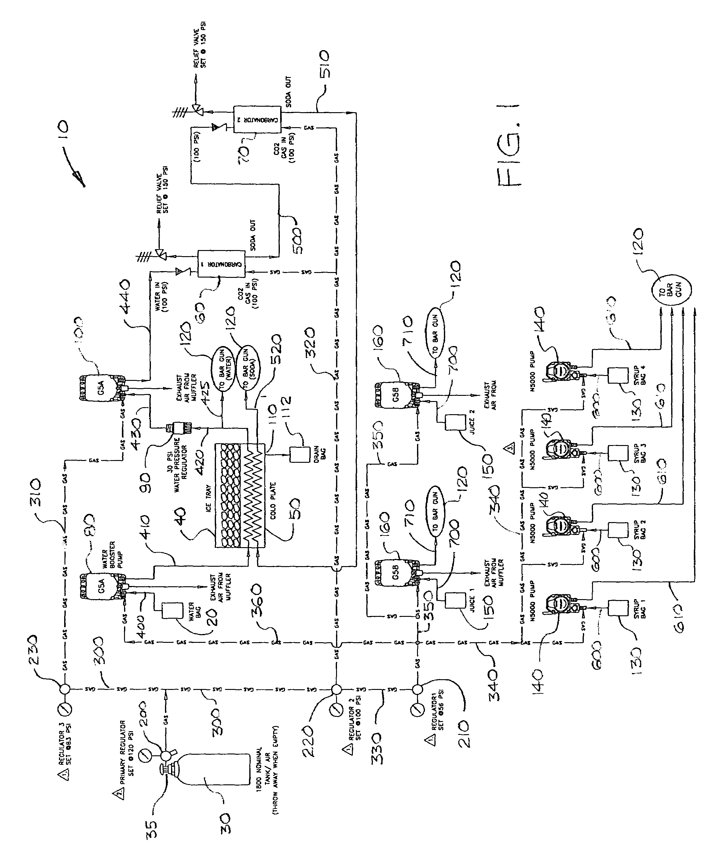
[0031]A schematic view of an embodiment of a compact and portable beverage dispensing system 10 according to the invention is shown in FIG. 1. The system includes a source of compressed carbon dioxide (CO2) gas 30, a flat water reservoir 20, a cold plate 50 with an ice tray 40, a water pressure regulator 90, a first motorless carbonator 60, a second motorless carbonator 70, and a plurality of carbonated beverage flavorant supply reservoirs 130, and a plurality of non-carbonated beverage supply reservoirs 150. The system is capable of carbonating flat water to between about 3.6 percent and about 4.2 percent CO2 by weight without electricity or an external pressurized water supply.

[0032]The system provides two sequential stages of carbonation. Flat water is first carbonated to between about 2.4 percent and about 3.6 percent by the first carbonator 60, and is then passed to the second carbonator 70 where the soda from the first carbonator 60 is further carbonated up to about 3.6 percen...


PUM


Abstract

A portable beverage dispensing system includes a supply of flat water and a supply of pressurized gaseous carbon dioxide. A first motorless carbonator is configured to receive a portion of the flat water and a portion of the carbon dioxide and to cause a portion of the carbon dioxide to dissolve in the flat water to produce partially carbonated soda. A second motorless carbonator is configured to receive a portion of the partially carbonated soda and a portion of the carbon dioxide and to cause a portion of the carbon dioxide to dissolve in the partially carbonated soda and to produce fully carbonated soda. The system also includes a dispenser for selectively dispensing the fully carbonated soda.

Description

TECHNICAL FIELD[0001]The invention generally relates to post-mix beverage dispensing systems, and more particularly relates to a compact and portable post-mix beverage dispensing system suitable for use on airplanes, railcars, or other applications where space and / or facilities are limited.BACKGROUND[0002]Post-mix beverage dispensing systems provide a convenient and efficient means for dispensing carbonated beverages to consumers. Such systems produce carbonated water, and mix flavored syrups with the carbonated water in desired ratios at a dispensing head or bar gun. Where such systems can be used, post-mixed beverages are highly cost-effective compared to more expensive pre-packaged carbonated beverages such as canned or bottled soft drinks.[0003]Presently, commercial airlines typically serve prepackaged beverages to their passengers. Prepackaged beverages such as canned beverages are stored at room temperature in a portable cart that is sufficiently narrow to pass down the aisles...

Claims


Application Information

Patent Timeline
Patent Type & Authority Patents(United States)
IPC IPC(8): B67D5/56B67D5/60B67D5/62B67D7/78B67D7/74B67D7/80
CPCB67D1/0021B67D1/0057B67D1/0084B67D1/0406B67D2210/00139
Inventor CRUNKLETON, III, JAMES T.DUPREE, DAVID W.
Owner INNOVATIVE SYST & CYLINDERS
Learn More