Annular disk for a sliding bearing

a technology of sliding bearing and annular disk, which is applied in the direction of sliding contact bearings, mechanical devices, transportation and packaging, etc., can solve the problems of objectionable noise and offending noise, and achieve the effect of small static friction and sliding friction, static friction, and large static friction

Inactive Publication Date: 2007-09-11
ZF FRIEDRICHSHAFEN AG
View PDF7 Cites 5 Cited by
  • Summary
  • Abstract
  • Description
  • Claims
  • Application Information

AI Technical Summary

Benefits of technology

[0007]By making the two annular elements of different materials, the second annular element can be fabricated of a material which, when the annular disk is installed, has a large static friction compared to the vehicle component or the cap. Conversely, the second annular element can be fabricated of a material which, when installed, has a very small static friction and sliding friction compared to the outer sleeve of the friction bearing. In this way, the static friction between the annular disk and the motor vehicle component or the cap can be greater than the static or sliding friction between the annular disk and the outer sleeve, allowing the annular disk to rotate relative to the outer sleeve, but not relative to the vehicle component and the cap. Therefore, the annular disk of the invention can produce a sliding bearing which prevents the generation of objectionable noise associated with conventional devices.
[0008]The first annular element can occupy approximately ⅔ of the height of the annular disk. Moreover, the seal and the first annular element are preferably fabricated from different materials, so that a material can be selected for the seal that provides a particularly effective sealing action. The sliding bearing can thereby also be protected over extended periods of time by preventing the lubricant to be flushed out of the bearing and / or humidity or contamination from entering the bearing.
[0009]When installed, the first end face of the first annular element preferably directly abuts the outer sleeve. The seal also directly abuts the outer sleeve to prevent humidity and contamination from entering the bearing interior and to prevent the lubricant in the sliding bearing from being flushed out. The seal can advantageously be fabricated from the same material as the second annular element and is preferably urged against the outer sleeve with a smaller force than the first annular element. The seal can have an annular shape and can be positioned concentrically with the annular disk and can be shaped, for example, as a sealing lip.
[0010]At least one slot that is continuous in the longitudinal direction is provided in the first annular element, with a portion of the second annular element forming the seal extending through the slot. Advantageously, the second annular element and the seal are here formed as a single piece and connected with each other through the slot. The part can therefore be manufactured cost-effectively, because the second annular element and the seal can be manufactured in a single manufacturing step. The edges of the slot can also provide mechanical stability to the seal, preventing bending of the seal, which increases the service life of the seal and contributes to a long-term sealing action. With this embodiment, the two annual elements are also formfittingly affixed to each other in the axial direction.
[0011]In particular, the material of the first annual element is harder than the material of the second annual element, so that the first annular element provides overall stability to the annular disk. Moreover, the material of the first annular element can also be harder than the material of the seal.
[0019]Advantageously, the annular disk abuts directly the outer shoulder and the outer sleeve and, in particular, is compressed between the outer shoulder and the outer sleeve, thereby preventing brief contact interruptions between the seal and the outer sleeve.

Problems solved by technology

When this sliding bearing is installed in a motor vehicle, a vehicle component and the annular disk can come into contact, so that the vehicle component can rotate relative to the annular disk while the motor vehicle is operated, which can cause offending noise.
A cap abutting the annular disk can also be fixedly secured on at least one end of the inner bush, allowing the cap to rotate relative to the annular disk and causing objectionable noise.

Method used


Image

  • Annular disk for a sliding bearing
  • Annular disk for a sliding bearing
  • Annular disk for a sliding bearing

Examples


Embodiment Construction

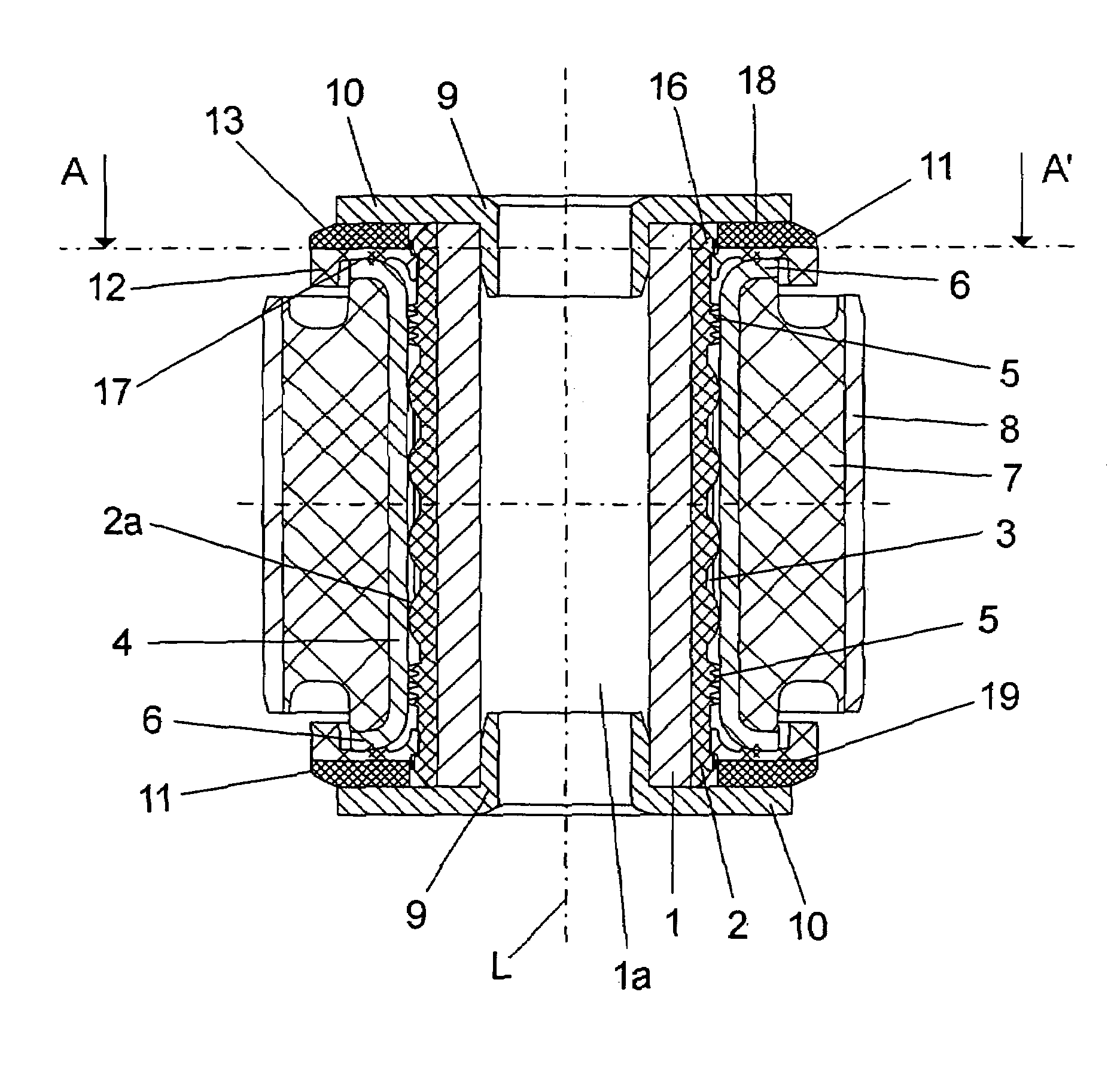
[0029]FIG. 1 shows a cross-sectional view of the sliding bearing with an inner sleeve 1, which can be made in particular out of steel, and a plastic sliding layer 2 surrounding the inner sleeve 1. The sliding layer 2 is attached to the inner sleeve 1 by a torque-proof connection. The outer surface 2a of the sliding layer 2 includes lubrication grooves 3, which are filled with a lubricant (not shown). The sliding layer 2 is surrounded by an outer sleeve 4 which can be made, in particular, of aluminum. The outer sleeve 4 abuts the sliding layer 2 via the interposed lubricant and is able to rotate about the longitudinal axis L of the bearing relative to the sliding layer and the inner sleeve 1. Moreover, annular sealing elements 5 are formed on the sliding layer, between which the lubrication grooves 3 are arranged in the longitudinal direction L.

[0030]The ends of the outer sleeve 4 include radially outwardly oriented angled sections 6. An elastomeric body 7, which in turn is surrounde...


PUM


Abstract

The invention is directed to an annular disk for sliding bearing, with a first annular element 12 and a seal 23 arranged on the first end face 17 of the first annular element 12. A second annular element is attached to the second end face 19 of the first annual element 12. The two annular elements 12, 13 are made of different materials.

Description

BACKGROUND OF THE INVENTION [0001]The present invention is directed to an annular disk for a sliding bearing, with a first annual element and a seal arranged on the first end face of the first annular element.[0002]Such annular disks are known in the art. For example, DE 40 36 051 C1 discloses an elastic sliding bearing for a motor vehicle, with an inner bush and a plastic layer surrounding the inner bush, and an edge bead provided on the ends of the inner bush. The plastic layer is surrounded by an outer bush (outer sleeve), whereby a corresponding plastic disk (annular disk) is secured in the axial direction between the edge beads and the outer bush.[0003]When this sliding bearing is installed in a motor vehicle, a vehicle component and the annular disk can come into contact, so that the vehicle component can rotate relative to the annular disk while the motor vehicle is operated, which can cause offending noise. A cap abutting the annular disk can also be fixedly secured on at le...

Claims


Application Information

Patent Timeline
Patent Type & Authority Patents(United States)
IPC IPC(8): F16C17/10B60G7/00F16F1/38
CPCB60G7/00F16C27/02F16C2326/05F16F1/3835
Inventor WAGENER, KEITFANGMANN, THOMASFANGMANN, MICHAEL
Owner ZF FRIEDRICHSHAFEN AG
Why Eureka
Try Eureka