High gain broadband planar antenna

a broadband, high-gain technology, applied in the direction of radiating elements, elongated active element feed, resonance antenna, etc., can solve the problem that the prior art cannot meet the high-gain requirement, and achieve the effect of enhancing the input impedance and bandwidth of the planar antenna and high gain

Active Publication Date: 2007-09-11
UNIVERSAL SCIENTIFIC INDUSTRIAL (SHANGHAI) CO LTD
View PDF5 Cites 22 Cited by
  • Summary
  • Abstract
  • Description
  • Claims
  • Application Information

AI Technical Summary

Benefits of technology

[0011]With such high gain broadband planar antenna and the design of the symmetric radiation unit and the reflector, the planar antenna can have a high gain of 6˜8 dBi and an operating bandwidth of 500 MHz. Since an end of the first radiation part, second radiation part, third radiation part, or fourth radiation part adopts a step design, therefore the input impedance and bandwidth of the planar antenna can be enhanced.

Problems solved by technology

Most of the present improved antenna structures can achieve good radiation efficiency and antenna gain in the operating bandwidth of the IEEE 802.11a / b / g, but the foregoing prior arts cannot satisfy the high gain requirement of a broadband (3.3˜3.8 GHz) required for the WiMAX technology, and the antenna gain of these prior arts is only in the range of 1.8˜2 dBi.

Method used


Image

  • High gain broadband planar antenna
  • High gain broadband planar antenna
  • High gain broadband planar antenna

Examples


Embodiment Construction

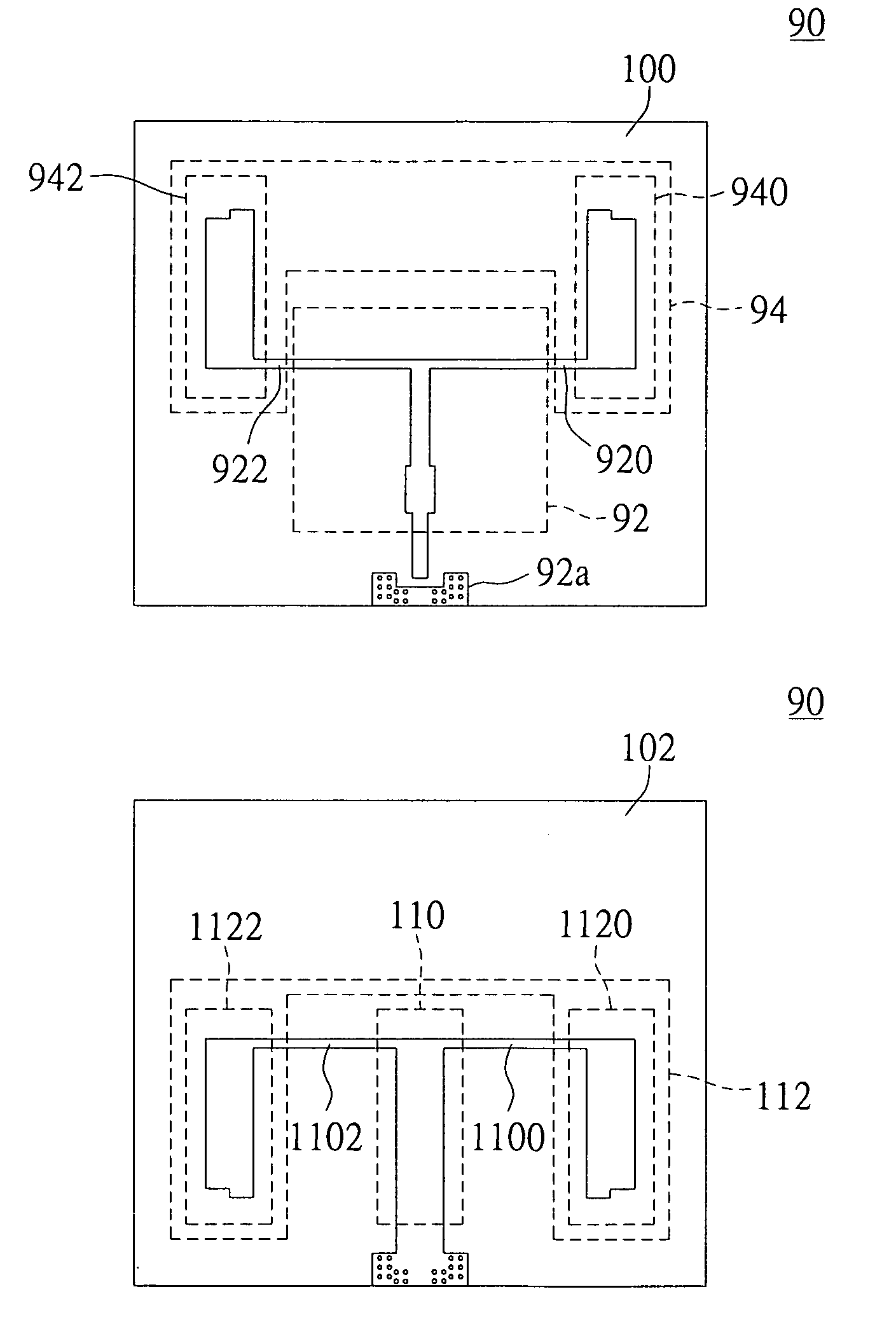
[0024]FIGS. 3 and 4 respectively show the front views of a first surface and a second surface of a microwave substrate of a high gain broadband planar antenna in accordance with the present invention.

[0025]Referring to FIG. 3 for the front view of a first surface according to a first preferred embodiment of the present invention, a first surface 100 of a microwave substrate 90 includes a microstrip circuit pattern having circuit layers, and the first surface 100 includes a first feed network unit 92, a first symmetric radiation unit 94, and a feed area 92a, wherein the first symmetric radiation unit 94 further includes a first radiation part 940 and a second radiation part 942.

[0026]Two lateral arms 920, 922 of the first feed network unit 92 are connected to the first radiation part 940 and the second radiation part 942 respectively, and a transmission line (not shown in the figure) is used to connect the first feed network unit 92 with the feed area 92a to constitute a complete bro...


PUM


Abstract

A high gain broadband planar antenna is provided for overcoming conventional antenna structure that cannot be applied to a high gain broadband. The antenna includes a microwave substrate having a first surface and a second surface, a first symmetric radiation unit having a first radiation part and a second radiation part disposed on the first surface, a second symmetric radiation unit having a third radiation part and a fourth radiation part disposed on the second surface, and at least one connecting unit connected to the microwave substrate and a reflector. An end terminal of each first radiation part, second radiation part, third radiation part and fourth radiation part adopts a step structure design. The planar antenna of the present invention can achieve a high gain broadband effect.

Description

BACKGROUND OF THE INVENTION[0001]1. Field of the Invention[0002]The present invention relates to a planar antenna structure, and more particularly to a high gain broadband planar antenna.[0003]2. Description of Related Art[0004]In recent years, the blooming of wireless communications gives rise to our increasingly higher requirements for the bandwidth and data transmission rate of wireless communications. As to the wireless local area network (Wi-Fi), the data transmission rate is improved from 2 MB and 11 MB up to 54 MB, but the transmitting distance is still restricted to a range from one hundred to two hundred meters. If the transmitting distance is extended to several kilometers, the Wi-Fi will be unable to work, and thus starting the development of a new WiMAX communication technology. The WiMAX is a type of wide area network (WAN) communications having a transmitting range up to 30 miles and according with the IEEE 802.16 standard. Most of the communication ranges of the wirel...

Claims


Application Information

Patent Timeline
Patent Type & Authority Patents(United States)
IPC IPC(8): H01Q9/28
CPCH01Q1/38H01Q9/38
Inventor AI, CHING-YUANCHIU, LI-CHI
Owner UNIVERSAL SCIENTIFIC INDUSTRIAL (SHANGHAI) CO LTD
Why Eureka
Try Eureka