Check patentability & draft patents in minutes with Patsnap Eureka AI!

Simple two-wire communication protocol with feedback status

Active Publication Date: 2007-09-11
EM MICROELECTRONIC-MARIN
View PDF7 Cites 1 Cited by
  • Summary
  • Abstract
  • Description
  • Claims
  • Application Information

AI Technical Summary

Benefits of technology

[0014]The object of the present invention is to overcome the afore cited drawbacks of both prior arts and, in particular, to provide a simple two-wire communication protocol for digitally trimmable electronic devices with several control signals.

Problems solved by technology

With only one control signal available, there is no freedom to modify the value of the capacitance or to monitor this value.
In both cases it is not worthy, the first alternative requires an additional terminal and the second one takes too much time.

Method used


Image

  • Simple two-wire communication protocol with feedback status
  • Simple two-wire communication protocol with feedback status
  • Simple two-wire communication protocol with feedback status

Examples


Embodiment Construction

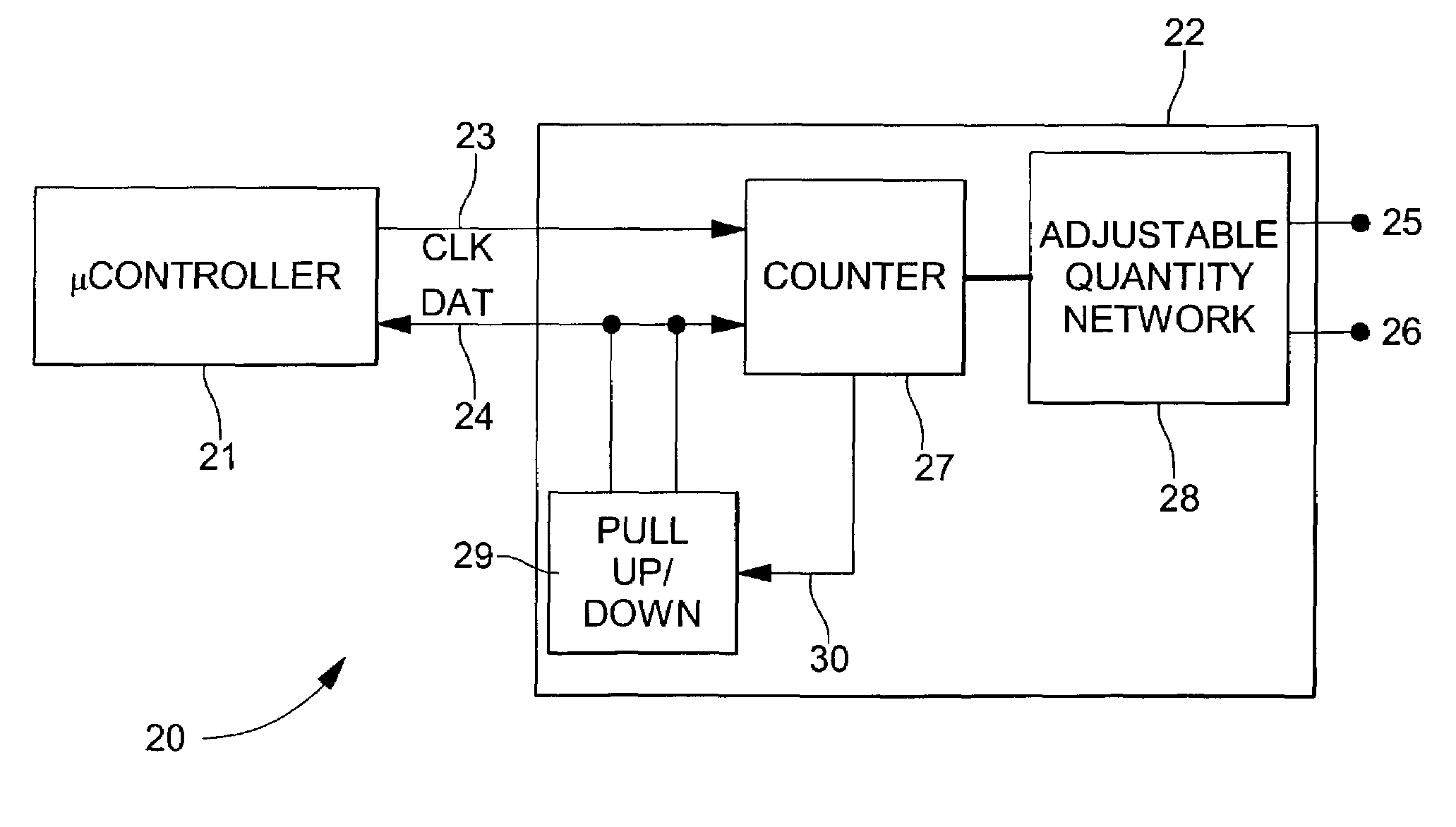
[0026]FIG. 4 shows a circuit 20 comprising a controller device, which may be in particular, a microcontroller 21 and a controlled device, which may be in particular, an electronic device 22 comprising a counter 27 and an adjustable quantity network. The microcontroller 21 and the counter 27 of the electronic device 22 are coupled by a clock line (CLK) 23 and a data line (DAT) 24. It is to be noted that the data line 24 may be tri-stated, as an input, an output or set to a high impedance state by the controller device.

[0027]When the controlled device 22 is connected to an external driver such as the microcontroller 21, only the microcontroller signals, which are stronger than the internal signals of the electronic device 22, can be read on the data line.

[0028]When the data line is set to a high impedance state by the controller device, internal pull-up or pull-down means 29, being no more in competition with an external driver, may set the data line 24 to a proper requested state. Th...


PUM


Abstract

A two-wire communication protocol between a controller device and a controlled device, wherein both devices are coupled by a clock line and a data line. The controller device sends control signals comprising N bits, N being greater than or equal to two, to the controlled device via the data line. Each bit of said control signals is latched onto the controlled device on consecutive edges of a clock signal sent by the controller device to the controlled device on the clock line.

Description

BACKGROUND OF THE INVENTION[0001]The present invention relates to a two-wire communication protocol between a controller device and a controlled device. The invention more particularly relates to digitally trimmable electronic devices such as a capacitor, a potentiometer, a current source, or other variable impedance elements.[0002]Both controller and controlled devices are coupled by a clock line and a data line. The controller device sends control signals comprising N bits, N being greater than or equal to two, to the controlled device on the data line.[0003]In the prior art, the document U.S. Pat. No. 5,084,667 discloses a variable impedance circuit for incorporation into electronic circuits in place of a potentiometer or similar mechanical variable impedance element. The impedance of the impedance circuit is set by electrical signals sent thereto. Once set, the impedance value is stored in a programmable non-volatile read only memory. When power is restored, this stored impedanc...

Claims


Application Information

Patent Timeline
IPC IPC(8): H04L7/00G06F13/42
CPCG06F13/4291
Inventor STAVER, DANIEL AWALL, BRUCE CARLTRAN, TUE
Owner EM MICROELECTRONIC-MARIN
Features
  • R&D
  • Intellectual Property
  • Life Sciences
  • Materials
  • Tech Scout
  • Unparalleled Data Quality
  • Higher Quality Content
  • 60% Fewer Hallucinations
Learn More