Method and apparatus for tooth bone conduction microphone

a microphone and tooth bone technology, applied in the field of tooth bone conduction microphone methods and apparatuses, can solve the problems of degrading its performance, not working all the time, and not accurately capturing spoken words

Active Publication Date: 2007-09-11
MAYUR TECH
View PDF14 Cites 95 Cited by
  • Summary
  • Abstract
  • Description
  • Claims
  • Application Information

AI Technical Summary

Problems solved by technology

Although usable, the Phraselator is highly vulnerable to typical military noise environment resulting in degradation of its performance.
The performance improves when the user holds the microphone very close to his mouth, however it still does not work all the time.
The microphone, due to the presence of typical military environment noise, does not accurately capture the spoken words.
Microphones pick up the acoustic signals coming from any direction from any source and cannot distinguish.
However, even the best directional microphones have limitations when used in military noise environment.
Conventional microphones cannot differentiate between the human voice and any other environmental sound.
They are unable to reproduce the spoken sounds faithfully.
In addition, the reverberation of the spoken sound introduces additional complexity in conventional microphones by way of repeated sound waves.
Although the above-referred devices have been successfully marketed, there are many drawbacks.
First, since the skin is present between the sensor and the bones the signal is attenuated and may be contaminated by noise signals.
This pressure results in discomfort for the wearer of the microphone.
Furthermore, they can lead to ear infection (in case of ear microphone) and headache (in case of scalp and jaw bone microphones) for some users.
The accelerometer protruded through the lips making the approach difficult to implement in practice.
The sensor is bulky and puts unbalanced load on the teeth making them useful only for experimental purposes, at the best.

Method used


Image

  • Method and apparatus for tooth bone conduction microphone
  • Method and apparatus for tooth bone conduction microphone
  • Method and apparatus for tooth bone conduction microphone

Examples


Embodiment Construction

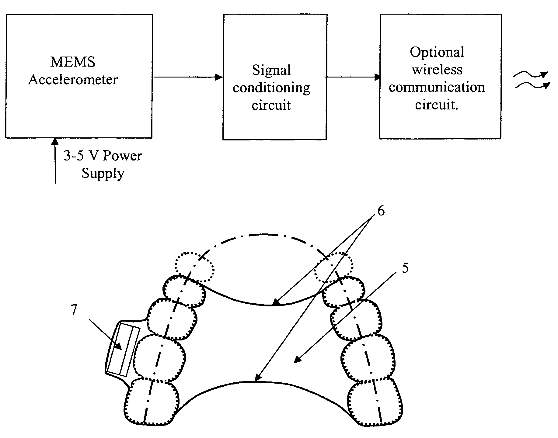
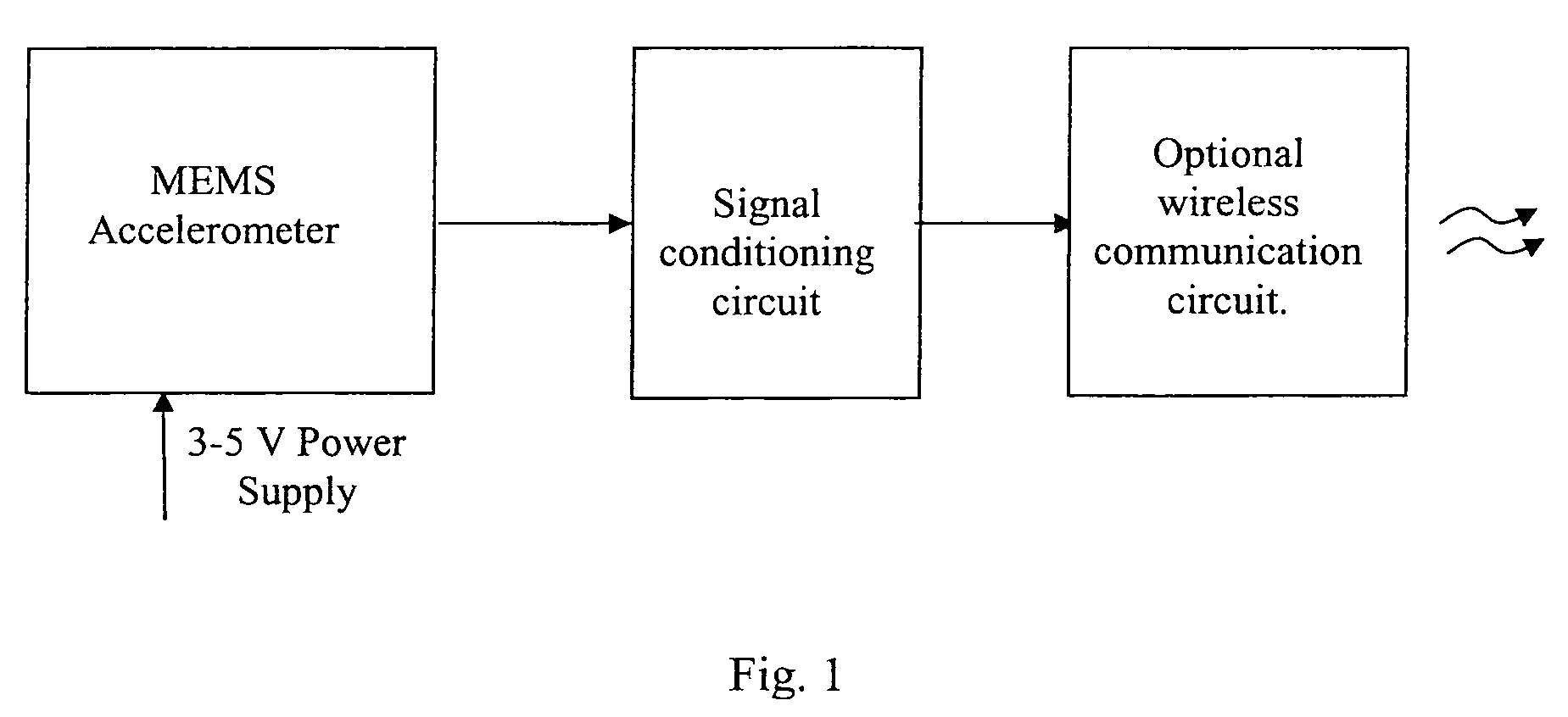
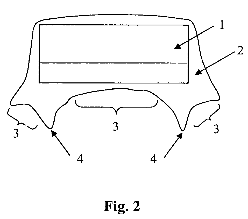
[0019]The present invention, a high sensitivity tooth microphone, uses the above-referred teeth vibration as the source of sound. The high sensitivity tooth microphone can include a high sensitivity accelerometer integrated with a signal conditioning circuit, and a probe. Optionally for wireless communication, a switch can be added to the microphone. An RF transmitter, power source, and Wi-Fi, Bluetooth, or other wireless communication technology can be used to transmit out of the mouth to a nearby receiver.

[0020]A free end of the probe is held in contact with the teeth during the action of speaking. The high sensitivity tooth microphone converts the teeth vibration produced by speaking to a proportional electrical signal. This electrical signal can either be directly fed to a speaker or stored for later retrieval and use or fed to a processor for translation.

[0021]There are several features of the high sensitivity tooth microphone that makes it ideal for minimizing or even eliminat...


PUM


Abstract

A tooth microphone apparatus worn in a human mouth that includes a sound transducer element in contact with at least one tooth in mouth, the transducer producing an electrical signal in response to speech and a means for transmitting said electrical signal from the sound transducer to an external apparatus. The sound transducer can be a MEMS accelerometer, and the MEMS accelerometer can be coupled to a signal conditioning circuit for signal conditioning. The signal conditioning circuit can be further coupled to a transmitter. The transmitter can be an RF transmitter of any type, an optical transmitter, or any other type of transmitter. In particular, it can be a bluetooth device or a device that transmits into a Wi-Fi network or any other means of communication. The transmitter is optional.

Description

[0001]This application is related to an claims priority from provisional patent application 60 / 461,601 filed Apr. 8, 2003 and to provisional patent application 60 / 517,746 filed Nov. 6, 2003. Applications 60 / 461,601 and 60 / 517,746 are hereby incorporated by reference.[0002]This invention was made with Government support under DAAH01-03-C-R210 awarded by the U.S. Army Aviation and Missile Command. The U.S. Government may have rights in this invention.BACKGROUND[0003]1. Field of the Invention[0004]The present invention relates generally to the field of microphones and more particularly to a tooth bone conduction microphone method and apparatus.[0005]2. Description of the Prior Art[0006]Conventional (air-conduction type) microphones are routinely used for converting sound into electrical signals. One such application is the Phraselator that is currently used by Department of Defense. The Phraselator primarily consists of a microphone, an automatic speech recognition module, a language t...

Claims


Application Information

Patent Timeline
Patent Type & Authority Patents(United States)
IPC IPC(8): H04R25/00H04R17/02
CPCH04R17/02H04R25/606H04R2460/13
Inventor ANJANAPPA, MUNISWAMAPPACHEN, XIABOGACKI, RUSSELL E.BABIK, ABDO J.
Owner MAYUR TECH
Why Eureka
Try Eureka