Brightness enhancement film having a light-guiding structure

a technology of light-guiding structure and brightness enhancement film, which is applied in the direction of optical waveguide light guide, waveguide, instrument, etc., can solve the problem of specific degree of warpage of brightness enhancement film in nature, difficulty in reducing the thickness of the entire substrate of the brightness enhancement film, and the inability of the light emission surface of the substrate to generate homogeneous refracted ligh

Active Publication Date: 2007-09-11
ZHEJIANG JINHUI OPTOELECTRONIC MATERIAL CO LTD
View PDF19 Cites 175 Cited by
  • Summary
  • Abstract
  • Description
  • Claims
  • Application Information

AI Technical Summary

Benefits of technology

[0014]The primary objective of this invention is to provide a brightness enhancement film having a light-refracting microstructure layer arranged on a light incident surface, and a light-guiding layer arranged on a light emission surface. The light-refracting microstructure can refract light, and subsequently, the light-guiding layer can guide the refracted light. Accordingly, the light-guiding layer can provide homogeneous light for enhancing brightness.
[0015]The secondary objective of this invention is to provide a brightness enhancement film further including a reinforcing layer arranged on the light emission surface, wherein the reinforcing layer is made from a transparent material having a rate of shrinkage which can be controlled to have a specific degree of hardness. Accordingly, the reinforcing layer of the brightness enhancement film can prevent occurrence of warpage and abrasion by another.
[0016]Another objective of this invention is to provide the brightness enhancement film having the light-refracting microstructure layer, wherein the light-refracting microstructure can be selected from prism units, micro-hemispheres, micro cones, micro rippled ridges, meandering microstructures or curved prism units. Accordingly, the light-refracting microstructure can improve light refraction of the brightness enhancement film.

Problems solved by technology

The light emission surface of the substrate cannot generate homogeneous refracted light due to the lack of any guiding means disposed on the light emission surface.
Another problem with the manufacture of such an additional light-guiding layer raises difficulty in reducing the entire thickness of the substrate of the brightness enhancement film.
Another problem with the manufacture of the substrate of the conventional brightness enhancement film generally forms a bottom surface which is an ordinary flat surface without forming any structure and opposite to the top surface on which to provide the microstructure of the prism units.
However, the top surface and the bottom surface disposed on the substrate of the brightness enhancement film are unmatched in structure which may cause a specific degree of warpage of the brightness enhancement film in nature.
This practice unavoidably causes warpage and abrasion between the surfaces of the separate brightness enhancement films, and disadvantageously affects quality and quantity of output of the brightness enhancement films.
Also, the light emission surface of the substrate cannot generate homogeneous refracted light if the light emission surface of the substrate is provided with no light-guiding layer to solve this problem.
Inevitably, another problem with the manufacture of such an additional light-guiding layer raises difficulty in reducing the entire thickness of the substrate of the brightness enhancement film.
There is an unavoidable need for improving such a brightness enhancement film in both enhancing homogeneous light and reducing a thickness of the substrate.
Even though the brightness enhancement film has the light-diffusing surface at its bottom side, the light-diffusing surface is still inadequate to prevent warpage of the brightness enhancement film in nature.
Furthermore, the light-diffusing particles of the brightness enhancement film protrude like raised particles on the light-diffusing surface and, thus, scrape the surface of another brightness enhancement film while piling upon each other.
Also, this practice unavoidably causes warpage and abrasion of the surfaces of the brightness enhancement films and disadvantageously affects quality and quantity of output of the brightness enhancement films.

Method used


Image

  • Brightness enhancement film having a light-guiding structure
  • Brightness enhancement film having a light-guiding structure
  • Brightness enhancement film having a light-guiding structure

Examples


first embodiment

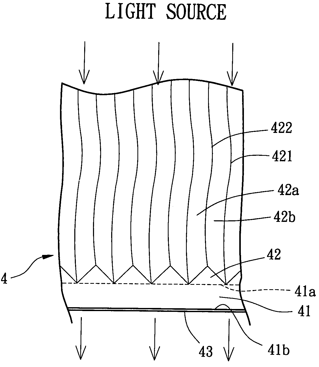
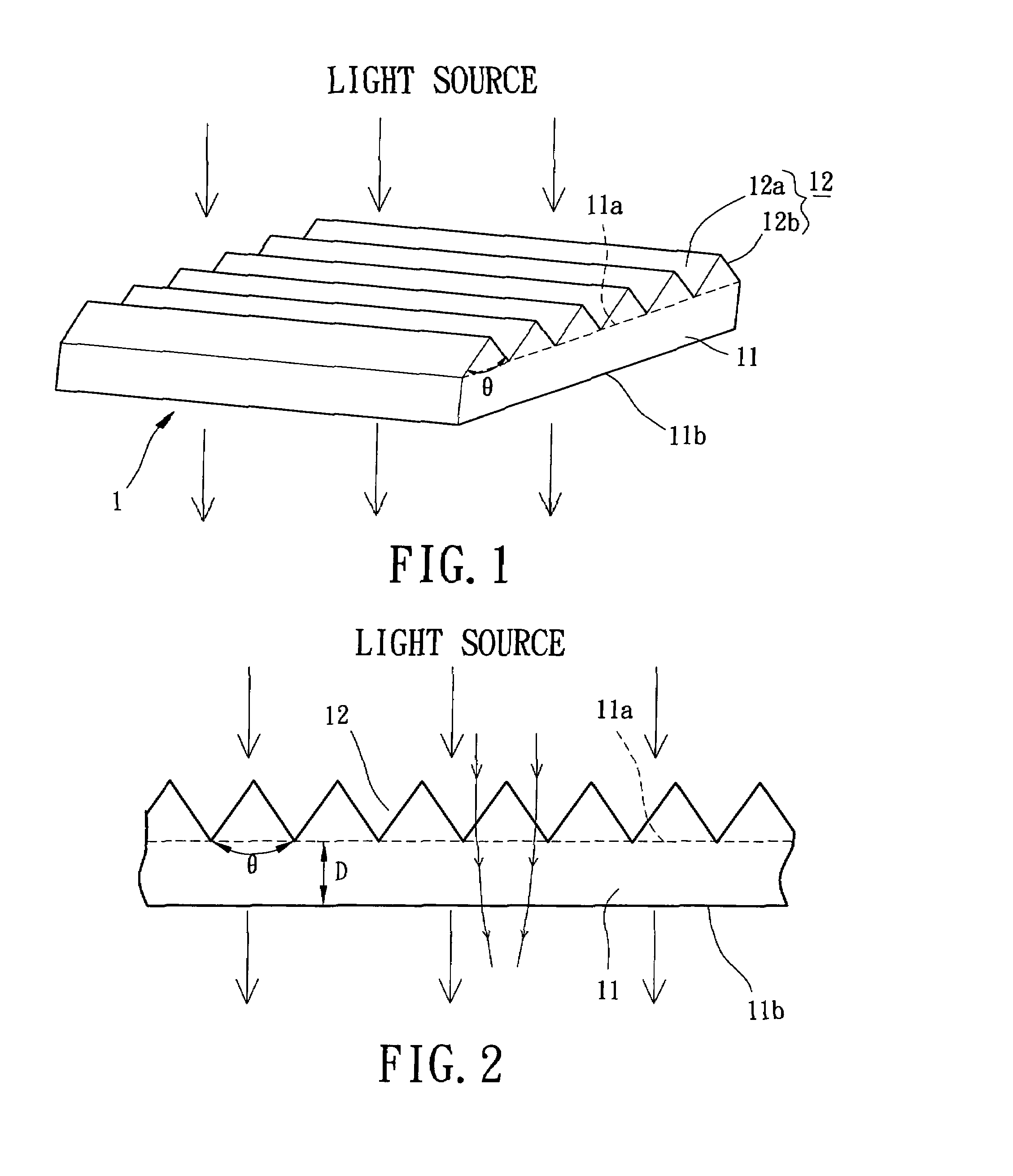
[0031]Referring initially to FIGS. 1 and 2, a brightness enhancement film 1 having a light-guiding structure in accordance with the present invention is a substrate constructed from a thin-sheet member. The substrate includes a light-guiding layer 11 and a plurality of prism units 12. Generally, the substrate has a light incident surface 11a (shown at a dotted line) at a first side of the light-guiding layer 11, and a light emission surface 11b at a second side of the light-guiding layer 11 which is opposite to the first side. The substrate is made from a transparent material to permit light to penetrate from the light incident surface 11a to the light emission surface 11b, and it can enhances brightness of light.

[0032]Still referring to FIGS. 1 and 2, a light-refracting microstructure layer of the brightness enhancement film 1 includes the prism units 12 provided with a light-refracting microstructure. The prism units 12 are arranged and juxtaposed on the light incident surface 11a...
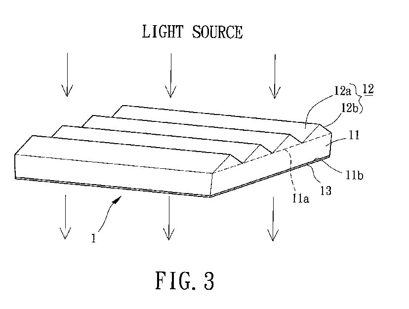
second embodiment

[0038]Still referring to FIG. 3, the manufacture of the brightness enhancement film 1 in accordance with the present invention shall be described in detail. The arrangement of the first flat inclined surfaces 12a and the second flat inclined surfaces 12b of the prism units 12 can be varied according to the design need. Such practice may, however, cause spontaneous warpage of the light-guiding layer 11. The reinforcing layer 13 can perform a relatively high degree of hardness that may alleviate the possibility of occurring warpage of the brightness enhancement film 1. Consequently, the brightness enhancement film 1 has a high degree of warpage resistance. Furthermore, the hardness of the reinforcing layer 13 can protect the light emission surface 11b of the light-guiding layer 11 against abrasion and scraping. Consequently, the brightness enhancement film 1 can carry out a high degree of abrasion resistance.

[0039]Still referring to FIG. 3, in manufacture, the light incident surface 1...


PUM

PropertyMeasurementUnit
thicknessaaaaaaaaaa
thicknessaaaaaaaaaa
included angleaaaaaaaaaa

Abstract

A brightness enhancement film having a light-guiding structure includes a substrate, which has a light-guiding layer and a plurality of light-refracting microstructures. The substrate has a light incident surface and a light emission surface opposite thereto. The light-refracting microstructures are arranged on the light incident surface of the substrate and are provided for varying surface curvatures to refract incident light. The light-guiding layer is arranged on the light emission surface of the substrate and is provided for guiding refracted light to generate homogeneous light to emit therefrom.

Description

BACKGROUND OF THE INVENTION[0001]1. Field of the Invention[0002]The present invention relates to a brightness enhancement film having a light-guiding structure for use in a liquid crystal display. Particularly, the present invention relates to the brightness enhancement film including a light-guiding layer and a light-refracting microstructure layer at either side thereof. More particularly, the present invention relates to the brightness enhancement film using the light-refracting microstructure to generate refracted light, and the light-guiding layer to guide the refracted light for providing homogeneous light.[0003]2. Description of the Related Art[0004]Referring initially to FIG. 1, U.S. Pat. No. 5,626,800, entitled “Prevention of Groove Tip Deformation in Brightness Enhancement Film,” discloses a brightness enhancement film including a substrate (i.e. base) and a plurality of prism units provided thereon. The prism units are arranged and juxtaposed on a top surface (i.e. light ...

Claims


Application Information

Patent Timeline
Patent Type & Authority Patents(United States)
IPC IPC(8): G02B6/10G02B6/34G02F1/1335
CPCG02B6/0053G02B6/0036G02B6/0038Y10S385/901
Inventor TANG, SHIH-CHIEH
Owner ZHEJIANG JINHUI OPTOELECTRONIC MATERIAL CO LTD
Why Eureka
Try Eureka