Random multi-stage automatic case sealer

a case sealer and random technology, applied in the field of box or case sealers, can solve the problems of box jamming, inability to determine the optimum position adjustment, etc., and achieve the effect of higher speeds

Inactive Publication Date: 2007-09-18
LE TUAN VINH
View PDF26 Cites 19 Cited by
  • Summary
  • Abstract
  • Description
  • Claims
  • Application Information

AI Technical Summary

Benefits of technology

[0007]In the present invention, the boxes progress in a non-stop manner through measuring, flap folding and flap sealing stages, so that higher speeds are achieved because a new box can enter the sealer and start to be processed while one or more boxes are still having operations performed on them in the sealer.

Problems solved by technology

A difficulty with the prior art devices, however, is that the boxes are often misshaped or underfilled or overfilled, so that they are not uniform in shape, so the sensors often cannot determine the optimum position adjustments.
The result is that the boxes get jammed in the apparatus shutting down the packaging line.
Another difficulty with some prior art case sealers is that they tend to be slow, in that if the boxes are of different sizes, a new box cannot enter or proceed through the case sealer until the previous box has cleared the sealer and the controls have been reset to be ready to receive the new box.

Method used


Image

  • Random multi-stage automatic case sealer
  • Random multi-stage automatic case sealer
  • Random multi-stage automatic case sealer

Examples


Embodiment Construction

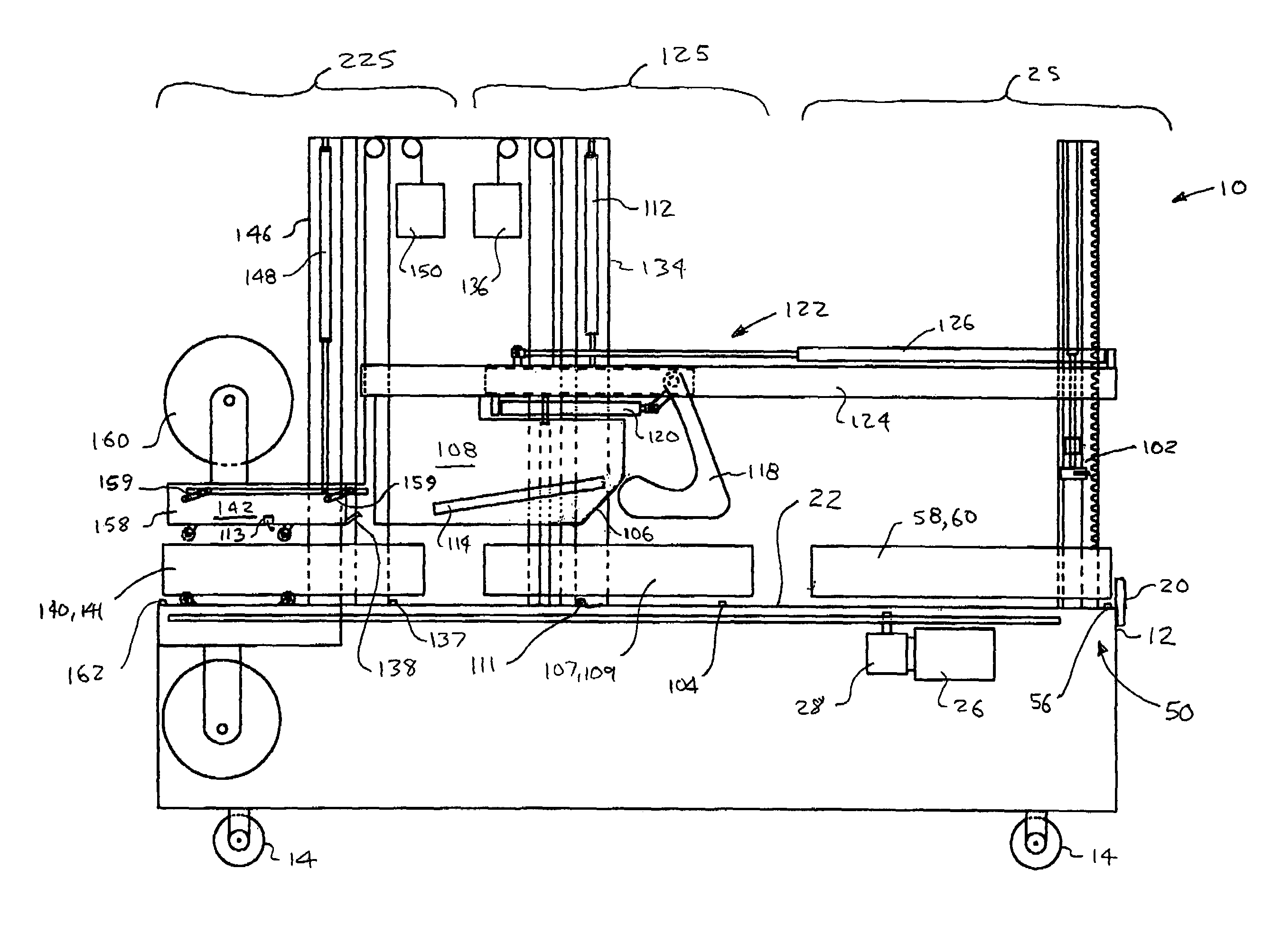
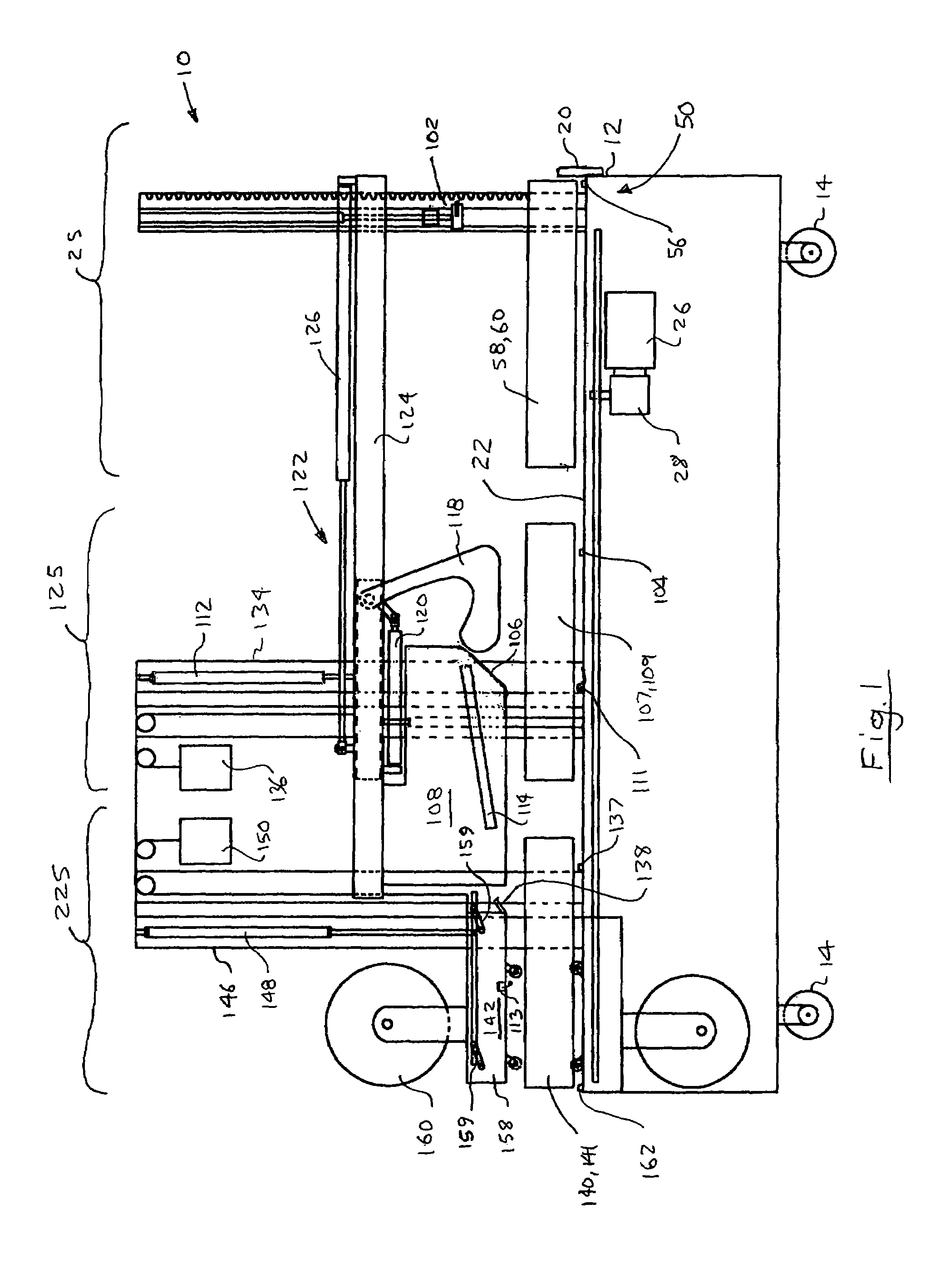
[0017]Referring to the drawings, a preferred embodiment of a case sealer according to the present invention is generally indicated in the drawings by reference numeral 10. Case sealer 10 includes a frame 12 mounted on casters 14, so that the case sealer is easily transportable or movable from one packaging line to another. Retractable feet (not shown) may be threadably mounted in frame 12 to engage the floor and make case sealer stationary, if desired. Alternatively, casters 14 can be of the locking type, for the same purpose. Frame 12 has a longitudinal axis 18 (see FIG. 2) which indicates the direction in which boxes or cartons or cases travel to be closed and sealed shut in case sealer 10.

[0018]Case sealer 10 is normally located adjacent to a packaging line (not shown) to close and seal, one at a time, filled boxes received from such a packaging line. However, boxes or cartons could be manually placed on case sealer 10 if desired. Where the cases are received from a packaging lin...


PUM


Abstract

A case sealer has a frame with a low friction conveyor upon which boxes are moved in series through three stages, each having an independent pair of spaced-apart, lateral conveyors that are linked together for inward and outward movement to accommodate the width of the box to be sealed. A first measuring stage measures the height, width and length of the box. A second flap folding stage has a floating head located over its lateral conveyors and is responsive to the height and width of the box and folds the box end and side flaps into a closed position. When a box enters the flap folding stage, the lateral conveyors in the measuring stage open to accept the next box, and based on the speed of the lateral conveyors and the measured length of the previous box, a gate allows the next box to enter the measuring stage as soon as the previous box has cleared the measuring stage.

Description

FIELD OF THE INVENTION[0001]This invention relates to box or case sealers for closing the open ends of cardboard boxes or cartons.BACKGROUND OF THE INVENTION[0002]In the packaging industry, many products are packed in cardboard boxes or cartons for shipping. Often, one end of the box, namely the bottom, is sealed shut before the box is filled, and after the box is filled, the open top end of the box usually has end and side flaps that are folded inwardly and downwardly. The box can be sealed by applying glue to the inside of the mating surfaces of the folded flaps prior to them being folded shut, or by applying tape to the outside of the flaps after they have been folded shut.[0003]In many cases, the boxes are uniform in size, so providing apparatus that will fold the flaps and apply adhesive or tape thereto is not particularly difficult to do. The apparatus can be adjusted to suit the known width and the height of the boxes and there is usually no problem running the boxes through ...

Claims


Application Information

Patent Timeline
Patent Type & Authority Patents(United States)
IPC IPC(8): B65B7/20B31B1/00B65B51/00B65B57/00B65B59/00
CPCB65B7/20B65B59/00B65B51/02B65B51/06B65B59/005B65B59/02B65B2210/04B65B59/003
Inventor LE, TUAN VINH
Owner LE TUAN VINH
Why Eureka
Try Eureka