Slant engine

a technology of engine oil and slant, which is applied in the direction of auxillary lubrication, valve drive, lubrication of crankcase compression engines, etc., can solve the problems of high production cost, complex structure, and inability to work appropriately for crankcase lubrication, so as to improve the maintenance characteristics, prolong the maintenance period of engine oil, and improve the effect of lubricating performan

Inactive Publication Date: 2007-09-18
SUBARU CORP
View PDF4 Cites 3 Cited by
  • Summary
  • Abstract
  • Description
  • Claims
  • Application Information

AI Technical Summary

Benefits of technology

[0011]In view of the above circumstances, the first object of the present invention is to improve lubricating performance when the slant engine is used on a slope or uneven surface. Furthermore, the second object of the invention is to lengthen a maintenance period of engine oil of the slant engine so as to improve maintenance characteristics.
[0019]According to the slant engine of the present invention, if the engine stands on a slope or uneven surface in such a way that the reservoir oil tank is positioned lower than the bottom of the crankcase, the liquid level splashed by the scraper tends to rise. However, this invention can prevent an excessive agitating load from being applied to the scraper because the part of lubricant in the crankcase flows into the reservoir oil tank. Furthermore, if the engine is stands on a slope or uneven surface in such a way that the reservoir oil tank is positioned upper than the bottom of the crankcase, the liquid level splashed by the scraper tends to descend. However, this invention enables the scraper to effectively splash the lubricant because the lubricant in the reservoir oil tank flows into the crankcase.
[0020]As described above, this invention can improve the lubricant property even in the event that the slant engine stands on a slope or uneven surface. Furthermore, this invention can extend the maintenance period since the large quantity of lubricant is stored in the crankcase and the reservoir oil tank and therefore qualities of the lubricant are kept over the long time. Moreover, because the reservoir oil tank is provided outside the crankcase, the cooling of the lubricant is improved so as to prevent the lubricant from excessively heating up.

Problems solved by technology

Thus, when the slant engine is used in the foregoing condition, the scraper may be unable to reach to a liquid surface of the lubricant otherwise it may sink deeply into the lubricant so that it cannot work appropriately for the lubrication in the crankcase.
Furthermore, when the reservoir oil tank is formed outside the crankcase and the solenoid valve controls the passage to the reservoir oil tank depending on a signal from the sensor detecting the level of lubricant surface of the oil pan as shown in Japanese Patent Laid-Open No 11-81966, the structure becomes complicate and the production cost becomes high.
Furthermore, it is difficult to apply this structure to the slant engine.

Method used


Image

  • Slant engine
  • Slant engine
  • Slant engine

Examples


Embodiment Construction

[0028]A preferred embodiment of the present invention is explained with figures, however, the scope of the invention is not limited by the illustrated embodiments of the figures.

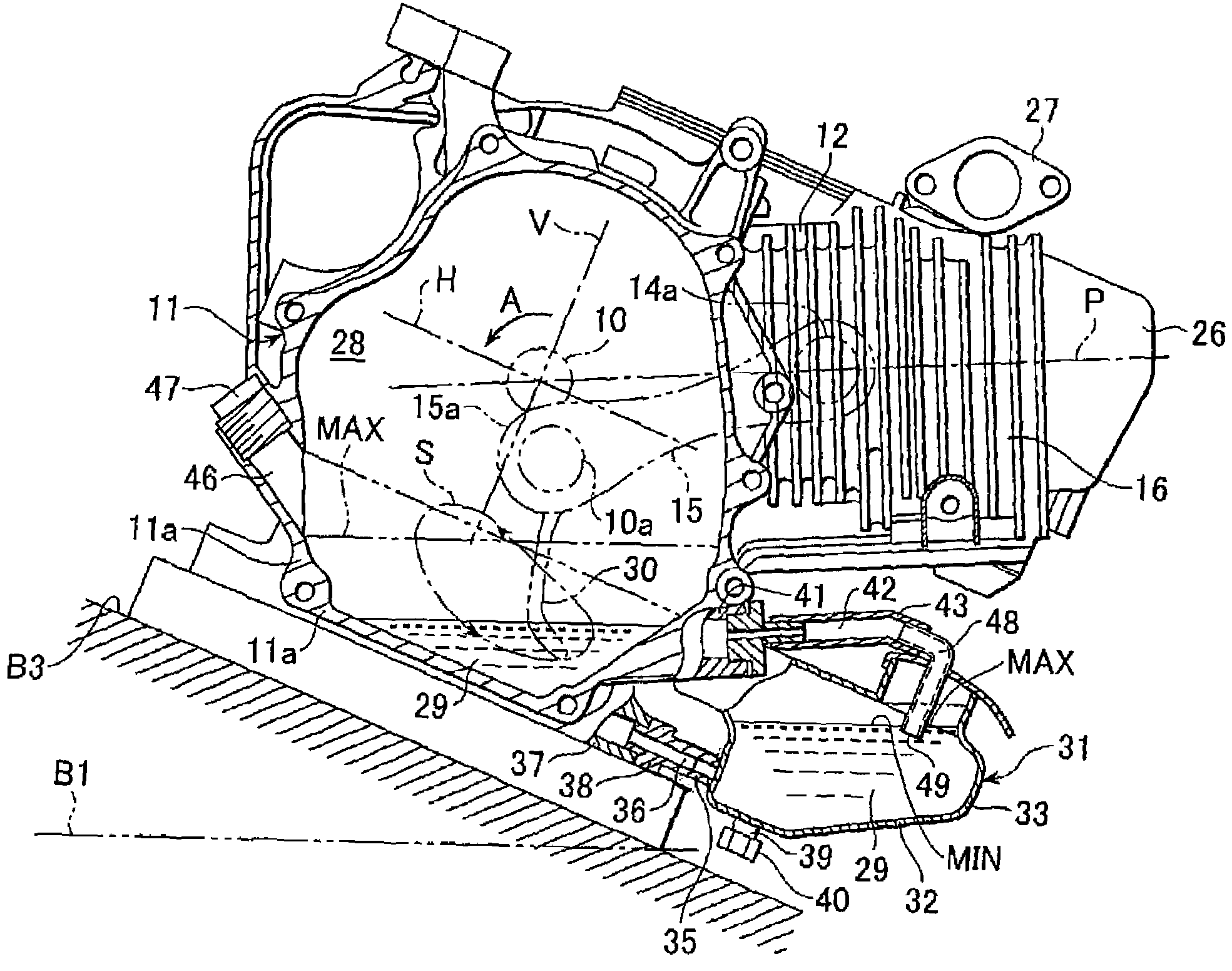
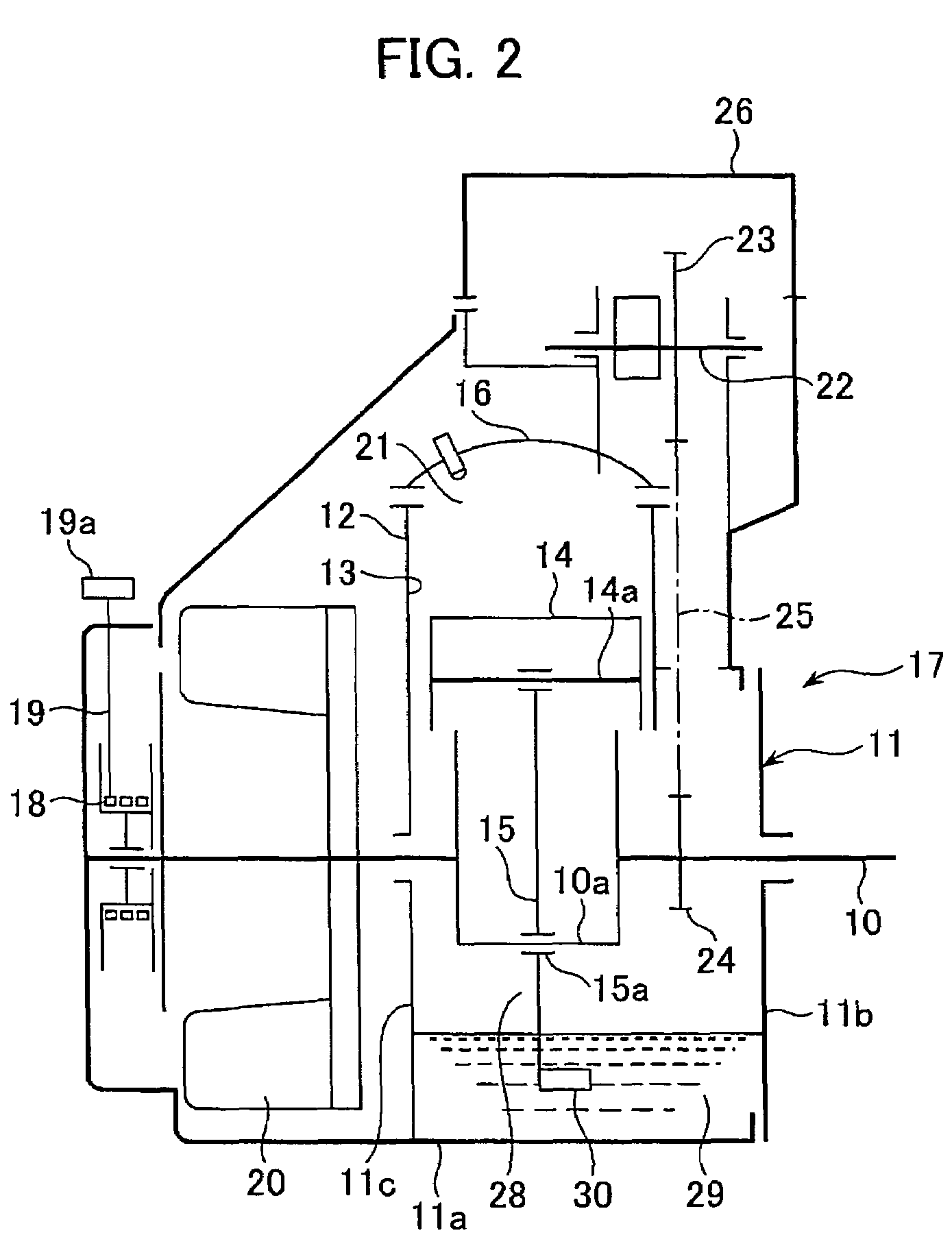
[0029]A slant utility engine according to the present invention is shown in FIG. 2. This slant engine is a four-stroke cycle one cylinder gasoline engine comprising a cylinder 12, a cylinder head 16 attached to the cylinder 12 and a crankcase 11. A crankshaft 10 is rotatably incorporated in the crankcase 11. The crankcase 11 comprises a main body 11a and a case cover 11b assembled to the main body 11a.

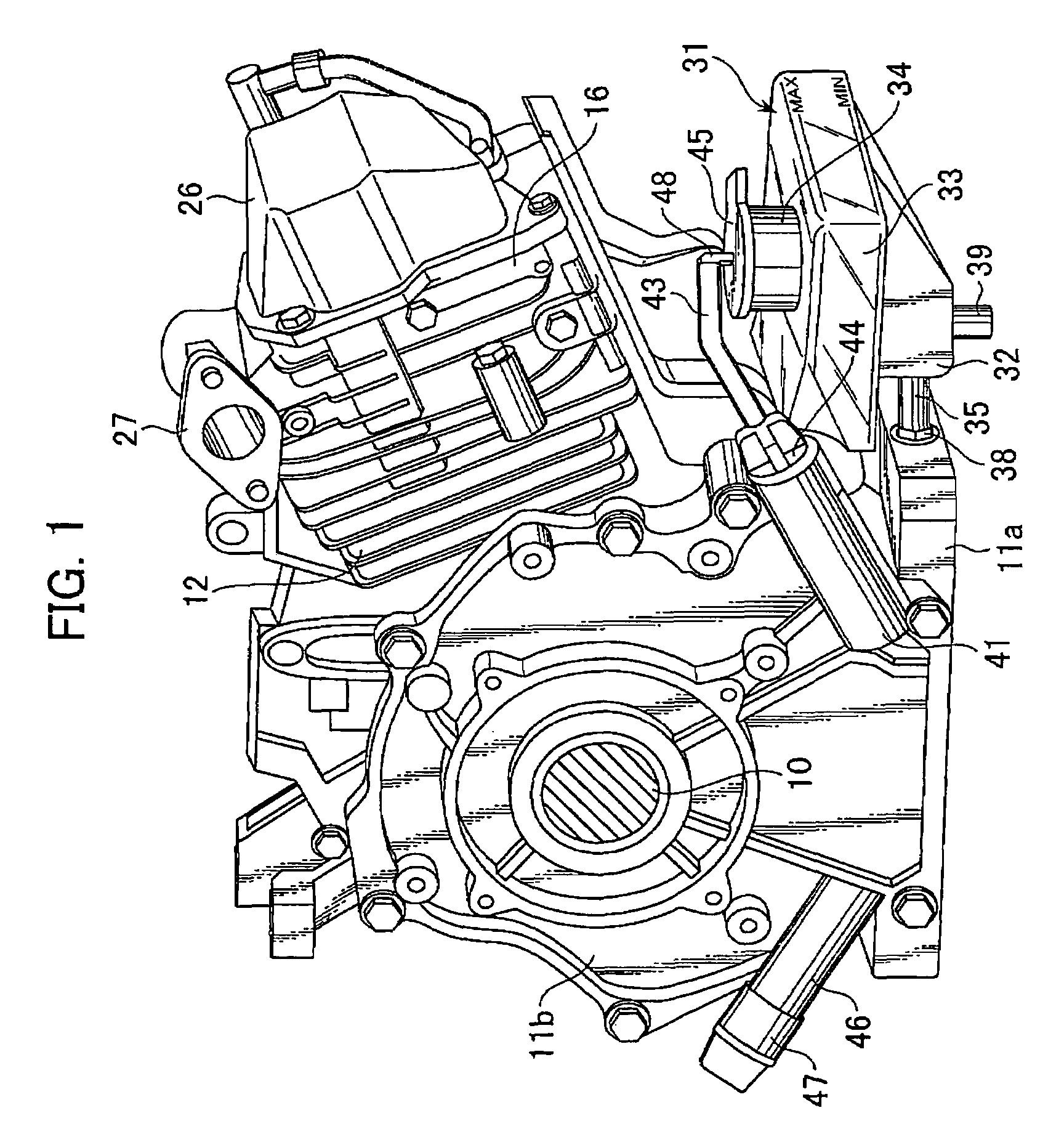
[0030]FIG. 1 shows the engine in the condition that the case cover 11b is assembled to the main body 11a. In this figure, the crankshaft 10 is eliminated. FIG. 3 shows the engine in the condition that the case cover 11b is removed from the main body 11a. The main body 11a has a portion in the cylindrical shape with a bottom part, a top part and right and left side walls as shown in FIG. 3. An end wall 11c is a...


PUM


Abstract

A slant engine for a utility engine which a cylinder is attached to the crankcase with slanted with respect to the a rotational direction of a crankshaft, comprises a reservoir oil tank formed outside of the crankcase at lower portion for reserving lubricant, a communication pipe connected to bottom portions of the reservoir oil tank and the crankcase for communicating the lubricant in the crankcase and the reservoir oil tank, and a vent pipe connected to both of the reservoir oil tank and the inside of the crankcase.

Description

CROSS REFERENCE TO RELATED APPLICATIONS[0001]The disclosure of Japanese Application No. 2005-031750 filed on Feb. 8, 2005 including the specification, drawing and abstract is incorporated herein by reference in its entirety.FIELD OF THE INVENTION[0002]This invention is related to a utility engine used as a power source for a generator etc, preferably a slant engine having a cylinder attached to a crankcase on a slant toward a rotational direction of the crankshaft.BACKGROUND OF THE INVENTION[0003]In a four-stroke cycle engine, a lubricant as engine oil is stored in a bottom of a crankcase. The lubricant is supplied to appropriate sliding portions that require lubrication, such as a bearing portion of a crankshaft incorporated in the crankcase, a joint portion between the crankshaft and a connecting rod, and a portion between a piston and cylinder bore. In a utility engine used as a power source for a generator or atomizer, the lubricant stored in the bottom of the crankcase is splas...

Claims


Application Information

Patent Timeline
Patent Type & Authority Patents(United States)
IPC IPC(8): F01M1/02
CPCF01L1/02F01L1/024F01M1/04F01L1/026F01M2001/126F02D29/06
Inventor FURUYA, AKIRA
Owner SUBARU CORP
Why Eureka
Try Eureka