Powder discharge system

a discharge system and powder technology, applied in the direction of burners, cleaning processes and apparatuses, thin material processing, etc., can solve the problems of negative effects of exhaust gases on the human body, the global environment, global warming, etc., and achieve the effect of prolonging the maintenance period of the circulating water tank and increasing the powder discharge ra

Active Publication Date: 2018-10-02
EBARA CORP
View PDF10 Cites 0 Cited by
  • Summary
  • Abstract
  • Description
  • Claims
  • Application Information

AI Technical Summary

Benefits of technology

[0007]It is therefore an object to provide a powder discharge system which can increase a discharge rate of powder and can prolong a maintenance period of a circulating water tank by crushing and floating powdery product such as silica deposited in the circulating water tank for a scrubber installed at a downstream side in an exhaust gas treatment apparatus.
[0011]According to the embodiment, because the eductor is disposed at a suitable place in the circulating water tank in which the powder is accumulated, and water is ejected from the eductor to the bottom of the circulating water tank, the powder aggregated on the bottom of the circulating water tank is crushed and floated, and thus the powder can be efficiently discharged together with drainage water. Therefore, the discharge rate of the powder can be increased and a maintenance period of the circulating water tank can be prolonged.
[0014]According to the embodiment, in the state where water level of the circulating water tank is lower than the suction port of the eductor, i.e., the water level is low, the pump is operated to supply water to the eductor, and only the water discharged from the nozzle is ejected from the eductor toward the bottom of the circulating water tank to crush the aggregated powder on the bottom of the circulating water tank, thus making a diameter of powder smaller. Then, in the state where water level of the circulating water tank is higher than the suction port of the eductor, the water discharged from the nozzle and the water sucked from the suction port are ejected from the eductor toward the bottom of the circulating water tank. Therefore, the powder on the bottom of the circulating water tank is further crushed and water in the circulating water tank is agitated, and thus the powder accumulated on the bottom of the circulating water tank is floated, and is then automatically discharged together with drainage water from a drainage port.
[0023](1) Because the eductor is disposed at a suitable place in the circulating water tank in which the powder is accumulated, and water is ejected from the eductor to the bottom of the circulating water tank while controlling water level of the circulating water tank, the powder aggregated on the bottom of the circulating water tank is crushed and floated, and thus the powder can be efficiently discharged together with drainage water. Therefore, the discharge rate of the powder can be increased and a maintenance period of the circulating water tank can be prolonged.
[0024](2) By supplying compressed air to the eductor periodically (or as needed), the suction port of the eductor can be prevented from being clogged. Therefore, the eductor does not need maintenance at all.

Problems solved by technology

Because exhaust gases such as the process gas, the cleaning gas or the like contain a silane-based gas, a halogen gas, a PFC gas or the like, such exhaust gases have negative effects on the human body and on the global environment such as global warming.
However, the bubbler tends to be clogged by the powder in structure at a nozzle portion for generating bubbles, and thus there is demand for a system which can discharge the powdery product accumulated on the bottom of the circulating water tank without using the bubbler.
Further, it is problematic that relatively small particles are floated and discharged by the bubbler, but large particles are not floated, thus being accumulated in the circulating water tank.

Method used


Image

  • Powder discharge system
  • Powder discharge system
  • Powder discharge system

Examples


Embodiment Construction

[0030]A powder discharge system according to embodiments will be described below with reference to FIGS. 1 through 5B. In FIGS. 1 through 5B, identical or corresponding parts are denoted by identical or corresponding reference numerals throughout views, and will not be described in duplication.

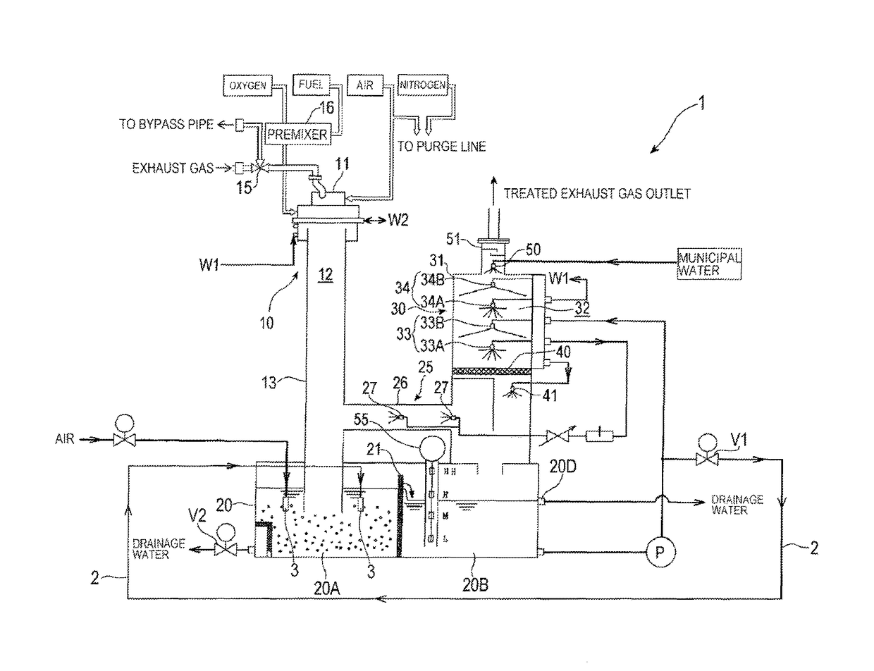
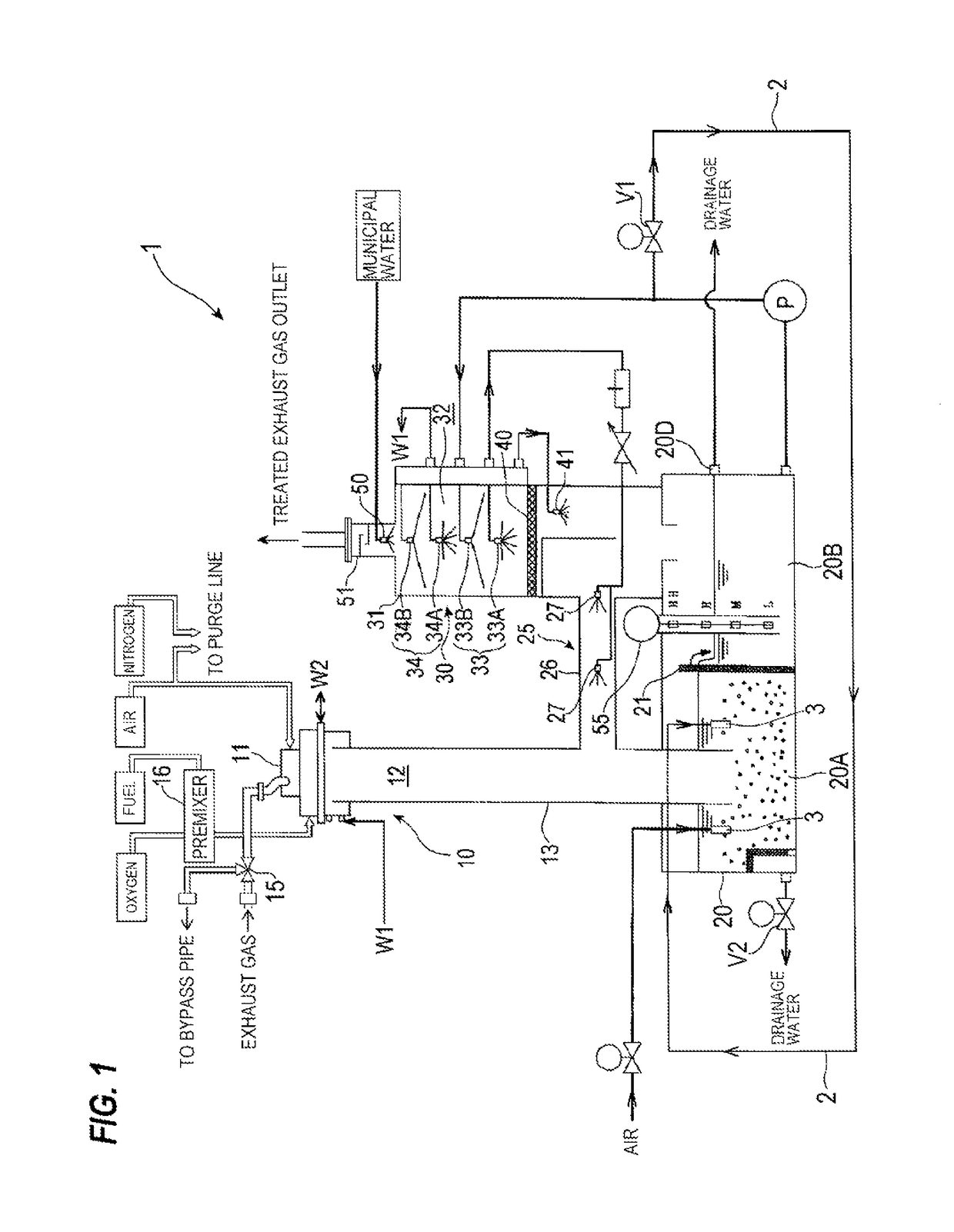
[0031]FIG. 1 is a schematic view showing an exhaust gas treatment apparatus 1 having a powder discharge system according to an embodiment. In FIG. 1, the exhaust gas treatment apparatus 1 comprises a combustion-type exhaust gas treatment apparatus by way of example. As shown in FIG. 1, the exhaust gas treatment apparatus 1 comprises a combustion-type heating treatment unit 10 for oxidatively decomposing an exhaust gas through combustion, and an exhaust gas cleaning unit 30 arranged at a stage subsequent to the heating treatment unit 10. The heating treatment unit 10 has a combustion chamber 12 for combusting the exhaust gas, and a burner 11 for generating flames swirling in the combustion cham...


PUM


Abstract

A powder discharge system is installed in a circulating water tank for collecting powder generated when an exhaust gas is treated in an exhaust gas treatment apparatus. The powder discharge system includes at least one eductor provided in the circulating water tank. The eductor has a nozzle configured to throttle a flow of water supplied from a pump for pumping water in the circulating water tank, a suction port configured to suck water in the circulating water tank into the eductor by utilizing a reduction of pressure generated when the flow of water is throttled by the nozzle, and a discharge port configured to eject the water sucked from the suction port together with the water discharged from the nozzle toward a bottom of the circulating water tank.

Description

CROSS REFERENCE TO RELATED APPLICATION[0001]This application claims priority to Japanese Patent Application No. 2013-126400 filed Jun. 17, 2013, the entire contents of which are hereby incorporated by reference.BACKGROUND[0002]In a semiconductor manufacturing process for manufacturing semiconductor devices, liquid crystal panels, LEDs or the like, a process gas is introduced into a process chamber which is being evacuated to perform various processes such as an etching process, a CVD process or the like. Further, the process chamber and exhaust apparatuses connected to the process chamber are cleaned periodically by supplying a cleaning gas thereto. Because exhaust gases such as the process gas, the cleaning gas or the like contain a silane-based gas, a halogen gas, a PFC gas or the like, such exhaust gases have negative effects on the human body and on the global environment such as global warming. Therefore, it is not preferable that these exhaust gases are emitted to the atmosphe...

Claims


Application Information

Patent Timeline
Patent Type & Authority Patents(United States)
IPC IPC(8): B08B9/093F23J15/04F23J15/06
CPCB08B9/0933F23J15/04F23J15/06F23D2900/00002Y10T137/4259F23J2217/60F23J2219/70F23J2219/80F23J2217/50
Inventor MIYAZAKI, KAZUTOMOIKEDA, HIROSHI
Owner EBARA CORP
Why Eureka
Try Eureka