
Stabilized earth structure reinforcing elements

a technology of earth structure and reinforcing elements, applied in mining structures, excavations, artificial islands, etc., can solve the problems of increasing the cost of inextensible reinforcing members, increasing the cost of reducing the relative stiffness of elements, and significantly more cost than using on-site materials, so as to achieve high configuration and reduce cost

Active Publication Date: 2007-09-18
ASHGROVE HLDG LLC
View PDF18 Cites 26 Cited by
  • Summary
  • Abstract
  • Description
  • Claims
  • Application Information

AI Technical Summary

Benefits of technology

"The present invention provides an improved reinforcing element configuration for a stabilized earth structure that allows for more interaction with the fill material than linear elements. The configuration can be used with any type of inextensible reinforcing member and can account for anticipated specific excessive loads in design of the structure. The invention also provides a yielding geometry for the reinforcing element that can reduce the modulus of elasticity at any point along the reinforcing member and reclassify the inextensible reinforcing member as an extensible reinforcing member. The invention also allows for the use of smaller cross sections in the elements for the same design life period and reduces cost over hot rolled section elements. The relatively high configurations of the invention allow for the use of rotated reinforcing strips in any plane and are relatively cost-effective."

Problems solved by technology

The obvious disadvantage of these new design codes is an increase in cost of the inextensible reinforcing members.
This method of reducing the elements relative stiffness has proven to be relatively costly.
Typically, this surrounding material has to be imported to the job from rock quarries at significantly more cost than using on site materials.
In their Special Research Study No. 8405, “Reinforced Earth Wall Strip Serviceability Study”, they show this was not successful.
U.S. Pat. No. 4,836,718 shows how to prolong the life of metallic elements by surrounding them with a cementous material, an effective but very costly method.
In U.S. Pat. No. 5,169,266 Sala discloses another very expensive way to extend the design life of the reinforcing elements beyond that of the standard galvanizied steel.
For all the above reasons corrosion of reinforcement elements in such structures represents a considerable problem in terms of the requirements of soil characteristics, and / or the cost of the anti corrosion inclusions on the reinforcing element.
Although this technology has been available since 1952, it has not been obvious to apply this same technology to particulate mass reinforcing elements.

Method used


Image

  • Stabilized earth structure reinforcing elements
  • Stabilized earth structure reinforcing elements
  • Stabilized earth structure reinforcing elements

Examples


Embodiment Construction

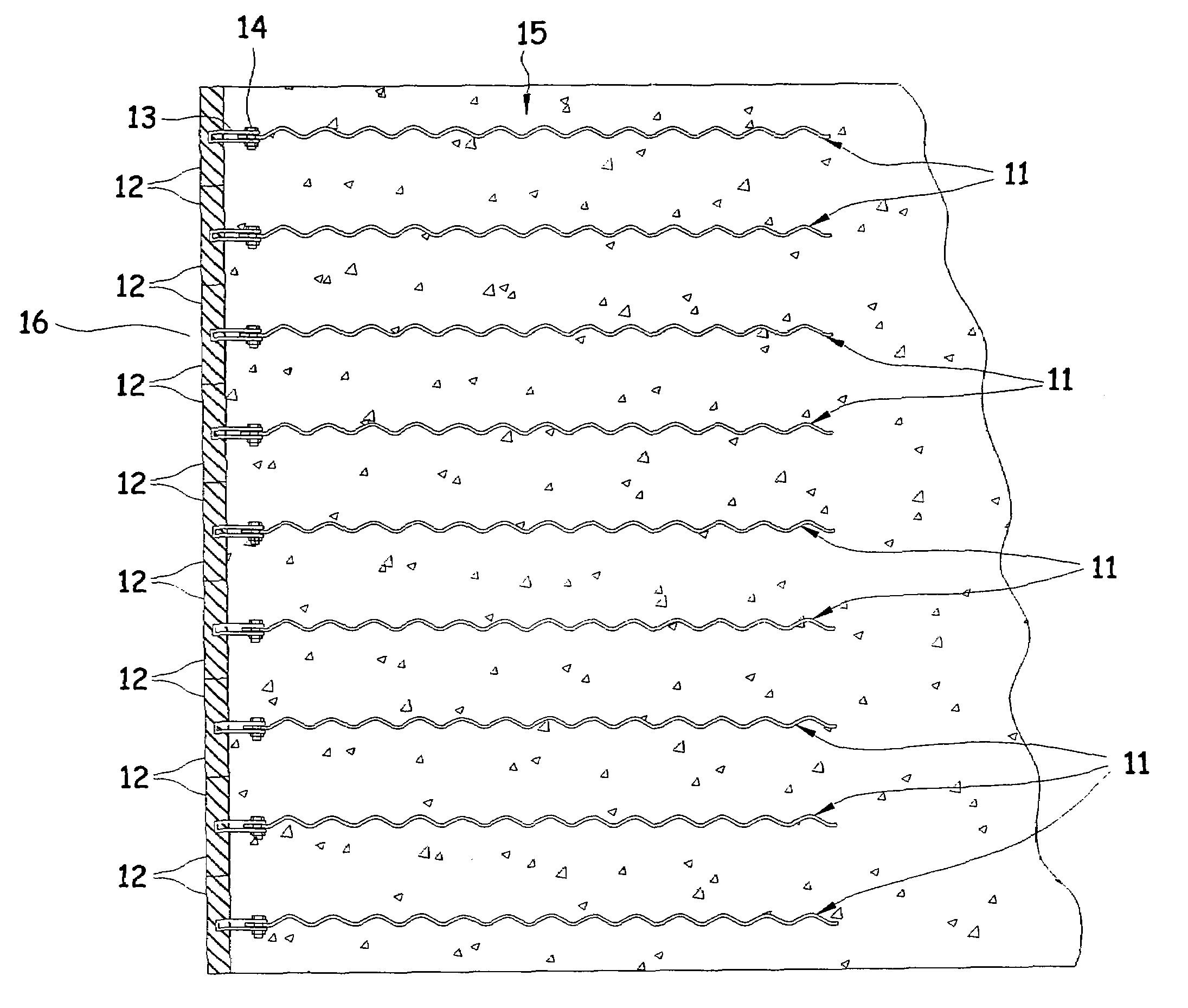
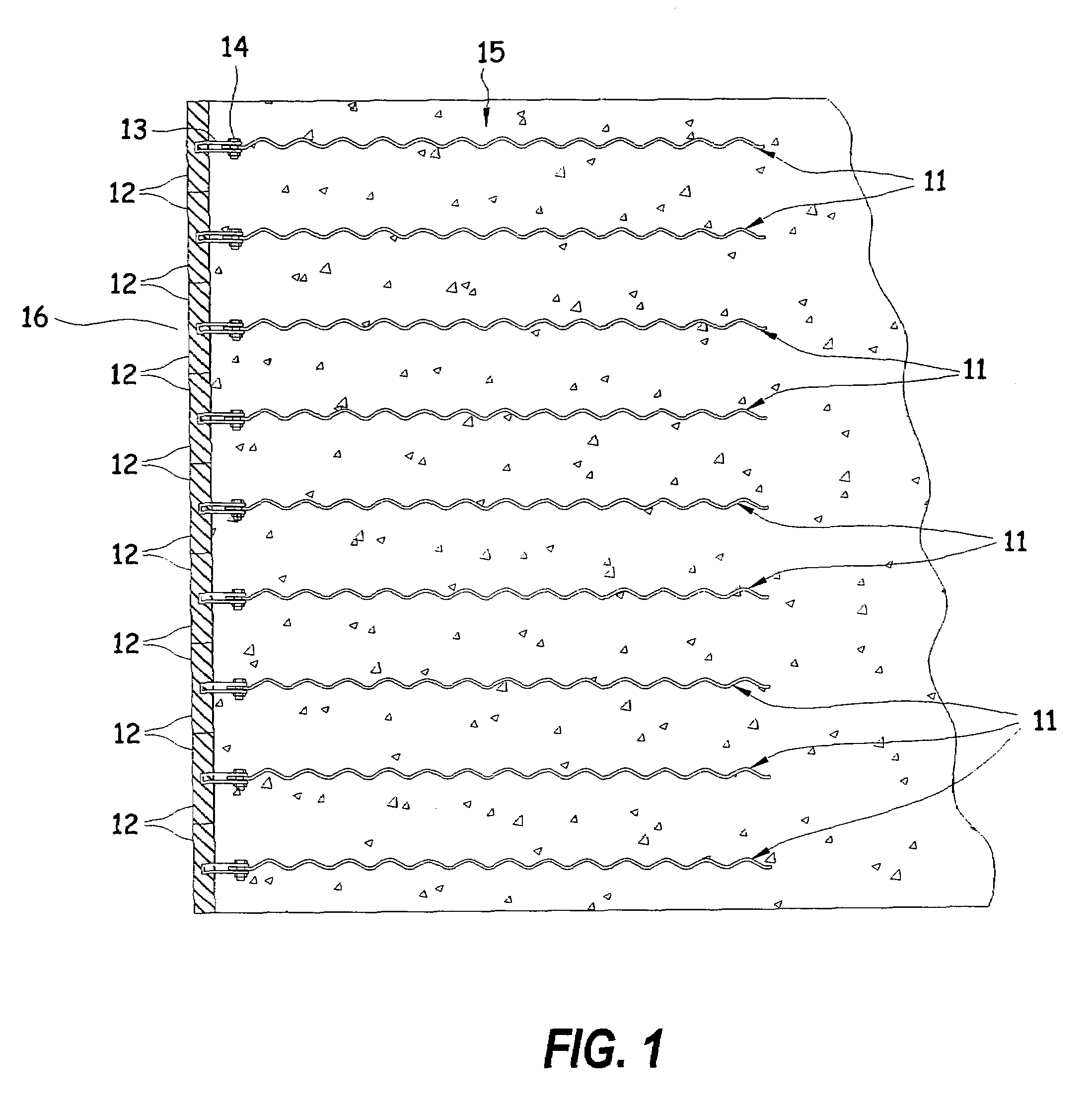
[0036]Referring to the FIGS. 1-10 for a clearer understanding of the invention, it may be seen that the preferred embodiment of the invention contemplates a non-linear stabilizing structure element. FIG. 1 shows a particle stabilizing structure. On the front of the structure is an earth retaining wall 16, formed by a plurality of facing elements 12. Behind the wall 16 is a mass of particulate fill material 15, which is stabilized by a plurality of horizontal reinforcing members 11 extending rearwardly from the facing elements 12 and embedded in the fill 15. The particles which make up the mass may include coal, clay, silt, sand, expanded shale, gravel, stones, glass or synthetic materials which may be used as a fill material. The configuration of the present invention may be used at any place along the reinforcing member, or may be used along the entire length of the member.

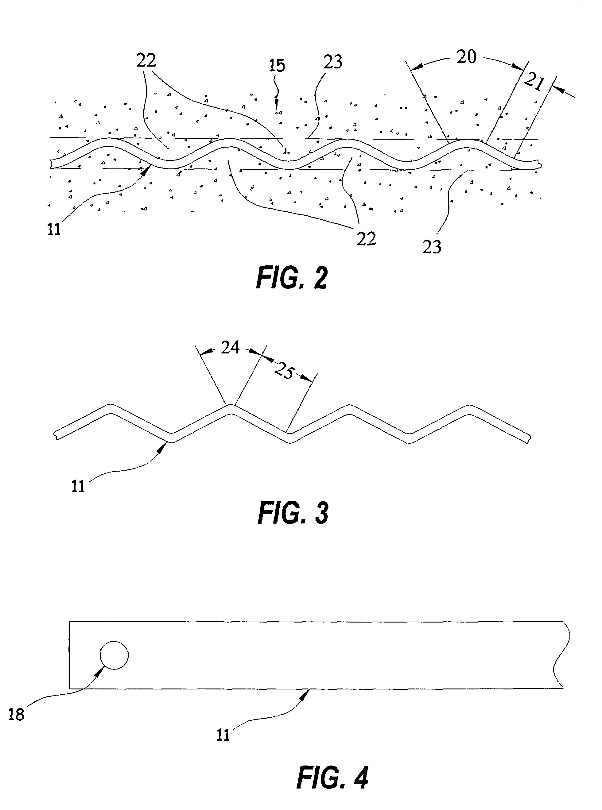
[0037]As shown in FIG. 2, the configuration of the reinforcing element 11 can be accomplished with a series of...


PUM


Abstract

A stabilizing element in a stabilized material particle structure, particularly an earthen embankment, wherein the material stabilizing elements that are inextensible (material with a higher modulus of elasticity than that of the surrounding particles) in composition nature but made more extensible because of its configuration. This extensibility gives the stabilizing elements the ability to mobilize more of the material shear resistance and adapt to current design standards under extensible type elements. The configuration also enhances the frictional engagement with the adjacent particles. The soil stabilizing elements are attached to facing elements and project into the compacted fill behind the facing. In some structures there may not be a facing element. Additionally, a material coating for metallic stabilizing elements that gives the elements improved corrosion protection, additional service life and / or expands the electrochemical environment in which they can be used.

Description

BACKGROUND OF THE INVENTION[0001]1. Field of the Invention[0002]The present invention relates generally to structures for supporting an underlying particle mass such as an earthen embankment or the like. The embankments may be materials other than soil or earth. This invention relates to the concepts of mechanically stabilized particle masses. The present invention relates to an improved construction for reinforcing elements used in forming retaining walls and earthen slopes. More particularly, the present invention may be described as a reinforced earthen structure wherein reinforcement is configured so as to utilize the earth friction and / or the passive resistance between the particles and the reinforcing element. The configuration also decreases the relative stiffness of the reinforcing element making the design of such structures require less applied load to the reinforcing member. In yet another aspect of the invention the structure is characterized by reinforcing members havin...

Claims


Application Information

Patent Timeline
Patent Type & Authority Patents(United States)
IPC IPC(8): E02D29/02
CPCE02D29/0233E02D29/0241
Inventor BROWN, RICHARD
Owner ASHGROVE HLDG LLC
Learn More