
Cable cord locating element

a technology of locating elements and cables, applied in the direction of coupling bases/cases, line/current collector details, coupling device connections, etc., can solve the problems of poor quality of electronic connectors, poor yield, and inconfusion of electronic connector production, so as to facilitate subsequent manufacturing processes and reduce time and labor costs.

Inactive Publication Date: 2007-09-18
JOINSOON ELECTRONICS MFG
View PDF7 Cites 35 Cited by
  • Summary
  • Abstract
  • Description
  • Claims
  • Application Information

AI Technical Summary

Benefits of technology

[0007]A primary object of the present invention is to provide a cable core locating element, so that the cores of a cable may be easily soldered to terminals of an electronic connector.
[0009]With the cable core locating element, disordered cable cores may be orderly and stably located in place to facilitate subsequent manufacturing processes, including core stripping and soldering of stripped cores to terminals of the electronic connector, so as to reduce the time and labor costs needed to produce the electronic connector.

Problems solved by technology

However, since it is very uneasy to rapidly and clearly distinguish the disordered cores from one another, a lot of time and labor is needed to correctly solder the bare wires of the cores to the terminals, bringing confusions to the production of the electronic connector.
Moreover, cores that have been soldered to corresponding terminals are subjected to undesired pull and breaking in the process of distinguishing and soldering the disordered cores, resulting in reduced good yield and poor quality of the produced electronic connectors.

Method used


Image

  • Cable cord locating element
  • Cable cord locating element
  • Cable cord locating element

Examples


Embodiment Construction

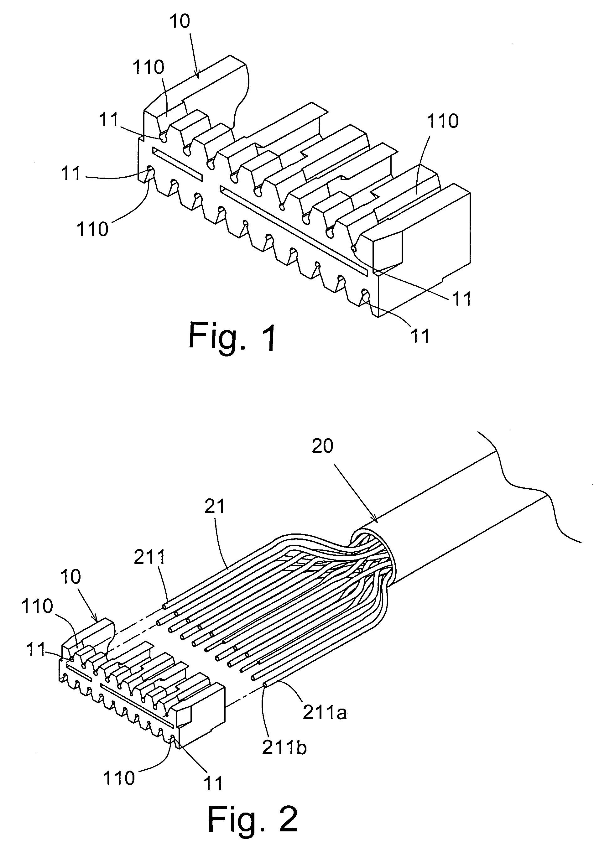
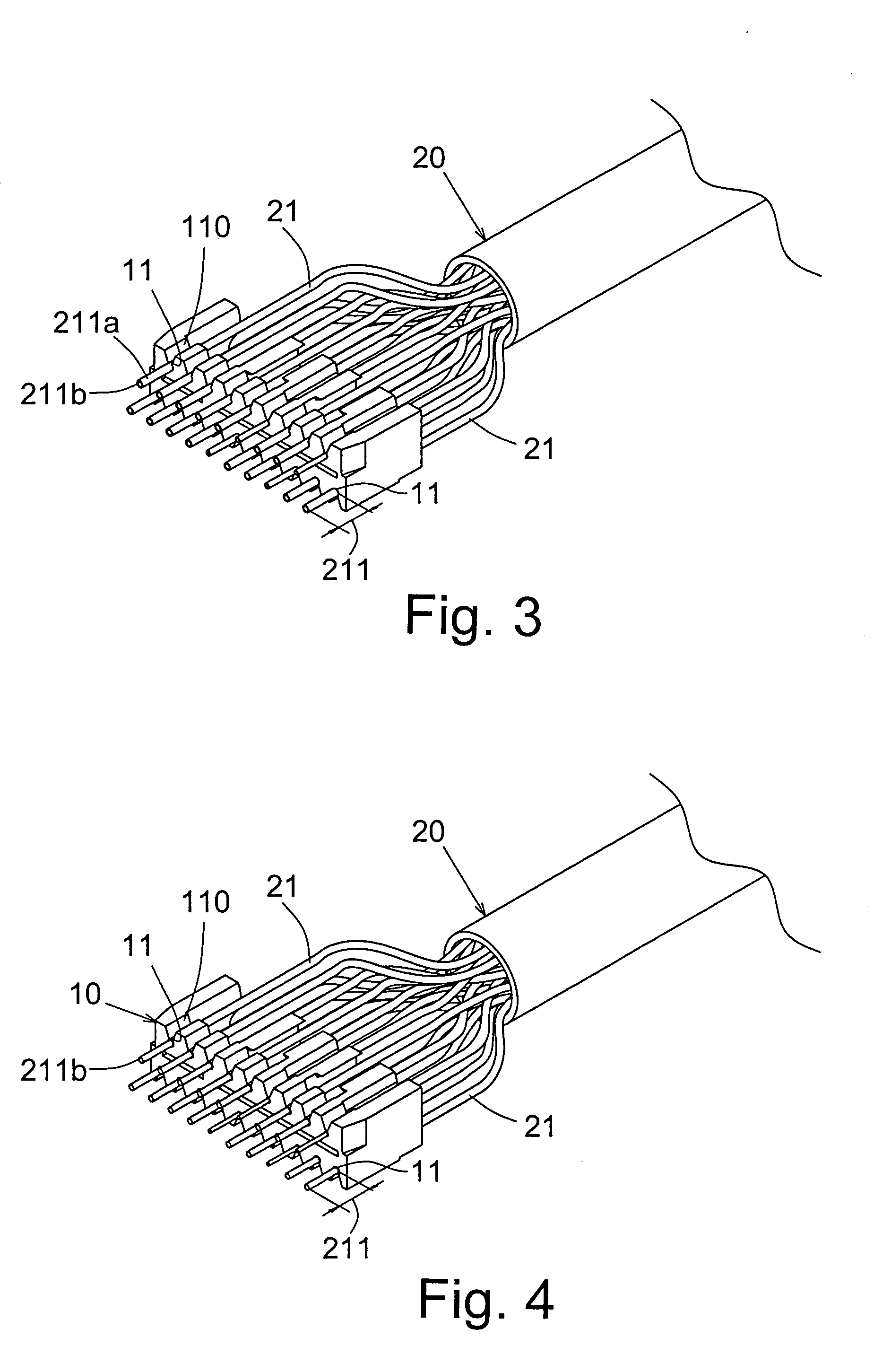
[0018]Please refer to FIGS. 1 through 7. A cable core locating element according to a preferred embodiment of the present invention includes a base 10 with a plurality of clamping slots 11, in each of which one of many cores 21 of a cable 20 may be clamped with a free end 211 of the clamped core 21 projected from a front side of the base 10. Each of the forward projected free ends 211 of the clamped cores 21 is then stripped to remove an insulating skin 211a and expose a bare wire 211b thereof. When the base 10 is assembled to an electronic connector 30, each of the stripped free ends 211 of the cores 21 is lapped over and soldered to a wire soldering section 311 on each of many terminals 31 of the electronic connector 30, so that the electronic connector 30 and the cable 20 are electrically connected to each other.

[0019]The base 10 shown in FIGS. 1 and 2 is made of an insulating material. Each of the clamping slots 11 has a generally V-sectioned profile and accordingly an expanded ...


PUM


Abstract

A cable core locating element includes a base formed of a plurality of clamping slots for clamping one of many cores of a cable each, with a free end of the core projected from a front side of the base. When the free ends of the forward projected cores are stripped and the base is assembled to an electronic connector, the stripped free end of each of the cores is lapped over and soldered to a wire soldering section of one of many terminals of the electronic connector, so as to electrically connect the electronic connector to the cable.

Description

BACKGROUND OF THE INVENTION[0001]1. Field of the Invention[0002]The present invention relates to a cable core locating element, and more particularly to a cable core locating element for orderly and stably locating cores of a cable to be soldered to terminals of an electronic connector, so as to facilitate subsequent terminal soldering process in producing the electronic connector.[0003]2. Description of the Prior Art[0004]Electronic connectors that are currently employed in electronic signal transmission, such as high-definition multimedia interface (HDMI) and universal serial bus (USB) interface, typically include a terminal holding body, on which a plurality of terminals are mounted with a rear section of each of the terminals being separately soldered to one of many cores of a cable. Thereafter, the terminal holding body and the cable are enclosed in a pair of metal cases, and a rear part of the metal cases is covered with an insulating housing to complete the electronic connect...

Claims


Application Information

Patent Timeline
IPC IPC(8): H01R13/648H01R13/46H01R43/00H01R43/28
CPCH01R4/023H01R4/027H01R13/6581Y10S439/942
Inventor HUANG, CHING-YUANHO, HUO-I
Owner JOINSOON ELECTRONICS MFG
Learn More