Wear monitoring system with embedded conductors

a technology of conductors and wear monitoring, which is applied in the direction of liquid fuel engine components, non-positive displacement fluid engines, rotocraft, etc., can solve the problems of excessive wear of components, affecting the proper functioning of components, and unable to eliminate relative motion

Inactive Publication Date: 2007-09-18
SIEMENS ENERGY INC
View PDF46 Cites 78 Cited by
  • Summary
  • Abstract
  • Description
  • Claims
  • Application Information

AI Technical Summary

Benefits of technology

[0008]The second component contacts the surface of the first component such that at least the surface of the first component wears. As a result, a user can monitor the measurement device for changes in the measured electrical value indicating that the wear has progressed at least to the predetermined depth.
[0014]In one embodiment, a second conductor can be embedded in the first component at a predetermined depth beneath the first surface. The second conductor can be operatively connected to receive current from the power source such that an initially open circuit is formed. Thus, when the first surface is sufficiently worn such that the second surface contacts the second conductor, the circuit can be completed. The completion of the circuit can alert a user that the wear has progressed to at least the predetermined depth at which the second conductor is located.

Problems solved by technology

Relative motion between such components can result in excessive wear of the components.
Such component wear can ultimately affect the proper functioning of the components and the system or assembly of which they are a part.
However, there are many instances in which relative motion cannot be eliminated, such as in brake linings, gears, sliders and slip fits; wear is unavoidable in such cases.
However, there are many applications in which regular inspection is not feasible because of a number of factors including, for example, time, labor, cost and disruptions due to down time.

Method used


Image

  • Wear monitoring system with embedded conductors
  • Wear monitoring system with embedded conductors
  • Wear monitoring system with embedded conductors

Examples


Embodiment Construction

[0036]Embodiments of the present invention provide a system that can monitor the wear of a component. Embodiments of the invention will be explained in the context of various possible wear monitoring systems, but the detailed description is intended only as exemplary. Embodiments of the invention are shown in FIGS. 1-8, but the present invention is not limited to the illustrated structure or application.

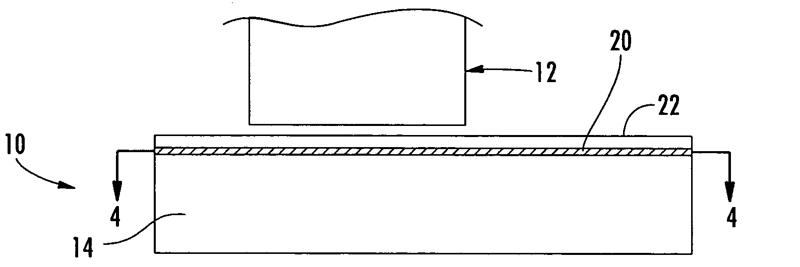
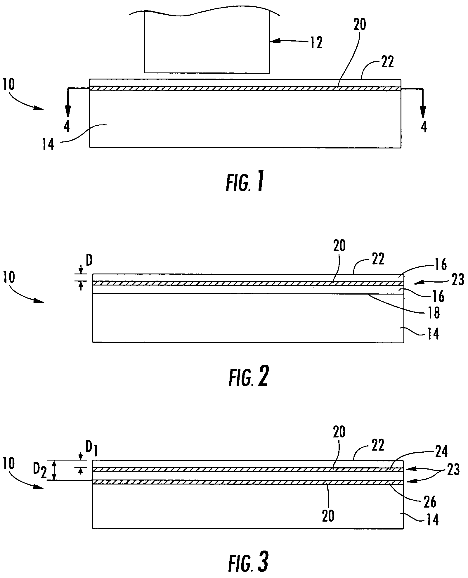
[0037]Referring to FIG. 1, a system according to aspects of the invention generally involves monitoring the wear of a component 10. While in use, the component 10 can contact another component 12, such as in sliding relation. Such contact may be substantially constant, periodic or irregular. The contact between the components 10, 12 can be an intentional or necessary part of the design, or the contact may be an unintentional consequence of an operational condition, such as vibration.

[0038]Because aspects of the invention have broad application, the component 10 can be almost any comp...


PUM

PropertyMeasurementUnit
frequenciesaaaaaaaaaa

Abstract

Aspects of the invention relate to a system for monitoring the wear of a component. A conductor can be embedded in the component at a depth from a surface of the component. In one embodiment, the conductor can be operatively connected to a power source to form an electrical circuit. The resistance across the conductor can be measured. As the component contacts a second component, the component can begin to wear. Once the wear progresses to the conductor, changes in the measured resistance can result. Thus, an operator can be alerted that the component has worn to a certain point and that service may be needed. Alternatively, impedance can be measured across the conductor. Because the dielectric permeability of the material surrounding the conductor can affect impedance, changes in impedance can occur as the surface material of the component is worn away.

Description

CROSS-REFERENCE TO RELATED APPLICATIONS[0001]This application is a Continuation-In-Part of U.S. patent application Ser. No. 10 / 252,236 filed Sep. 23, 2002 now U.S. Pat. No. 6,838,157.FIELD OF THE INVENTION[0002]The invention relates in general to component wear and, more particularly, to systems for monitoring component wear.BACKGROUND OF THE INVENTION[0003]In many applications, there can be two or more components in contact. Relative motion between such components can result in excessive wear of the components. Such component wear can ultimately affect the proper functioning of the components and the system or assembly of which they are a part.[0004]Wear can be controlled within acceptable levels in some instances by the use of lubricants, by material selection and / or by design features that limit the motion and / or geometry of the components. However, there are many instances in which relative motion cannot be eliminated, such as in brake linings, gears, sliders and slip fits; wear...

Claims


Application Information

Patent Timeline
Patent Type & Authority Patents(United States)
IPC IPC(8): B32B9/00C23C4/18C23C24/10C23C28/00F23M5/00F23M11/00F23R3/00
CPCC23C4/18C23C24/10F23M5/00F23R3/007G01N3/56F23M11/00Y10T428/12611Y10T428/24273F16D66/02
Inventor SABOL, STEPHEN M.SUBRAMANIAN, RAMESH
Owner SIEMENS ENERGY INC
Why Eureka
Try Eureka