
Apparatus for controlling operation of reciprocating compressor, and method therefor

a reciprocating compressor and apparatus technology, applied in the direction of motor/generator/converter stopper, dynamo-electric converter control, instruments, etc., can solve the problems of non-linear characteristics of motor constants and the inability to control the stroke of reciprocating compressors normally, so as to prevent over-saturation of magnetic flux density and reduce operation errors

Active Publication Date: 2007-09-18
LG ELECTRONICS INC
View PDF29 Cites 14 Cited by
  • Summary
  • Abstract
  • Description
  • Claims
  • Application Information

AI Technical Summary

Benefits of technology

The present invention provides an apparatus and method for controlling the operation of a reciprocating compressor that can reduce errors in estimating the stroke of the compressor. This is achieved by preventing over-saturation of the magnetic flux density in the motor's coil and increasing or decreasing a predetermined stroke reference value based on the magnetic flux saturation constant of the motor. The control unit then controls the voltage applied to the motor of the compressor based on the generated stroke reference value and the stroke estimated value. This results in improved accuracy and efficiency of the compressor's operation.

Problems solved by technology

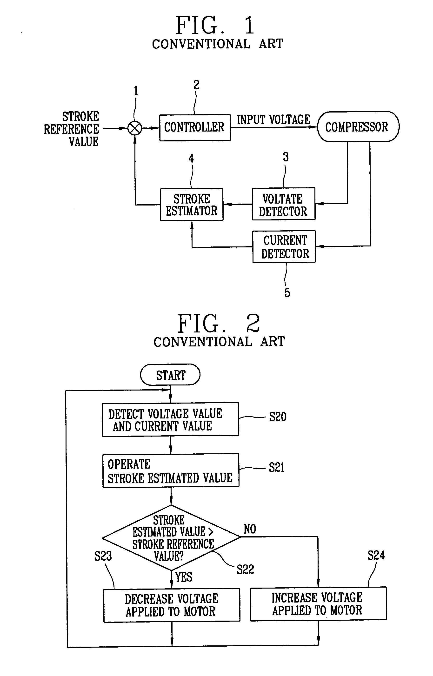
However, in the conventional apparatus for controlling the operation of the reciprocating compressor and the method therefor, when the load on the motor of the reciprocating compressor is overloaded, a magnetic flux density generated in a coil of the motor is saturated, and thus the motor constant has non-linear characteristics.
As a result, errors are generated due to the motor constant in the operation of the stroke estimated value of the reciprocating compressor, and thus the stroke of the reciprocating compressor is not normally controlled.

Method used


Image

  • Apparatus for controlling operation of reciprocating compressor, and method therefor
  • Apparatus for controlling operation of reciprocating compressor, and method therefor
  • Apparatus for controlling operation of reciprocating compressor, and method therefor

Examples


Embodiment Construction

[0035]Reference will now be made in detail to the preferred embodiments of the present invention, examples of which are illustrated in the accompanying drawings.

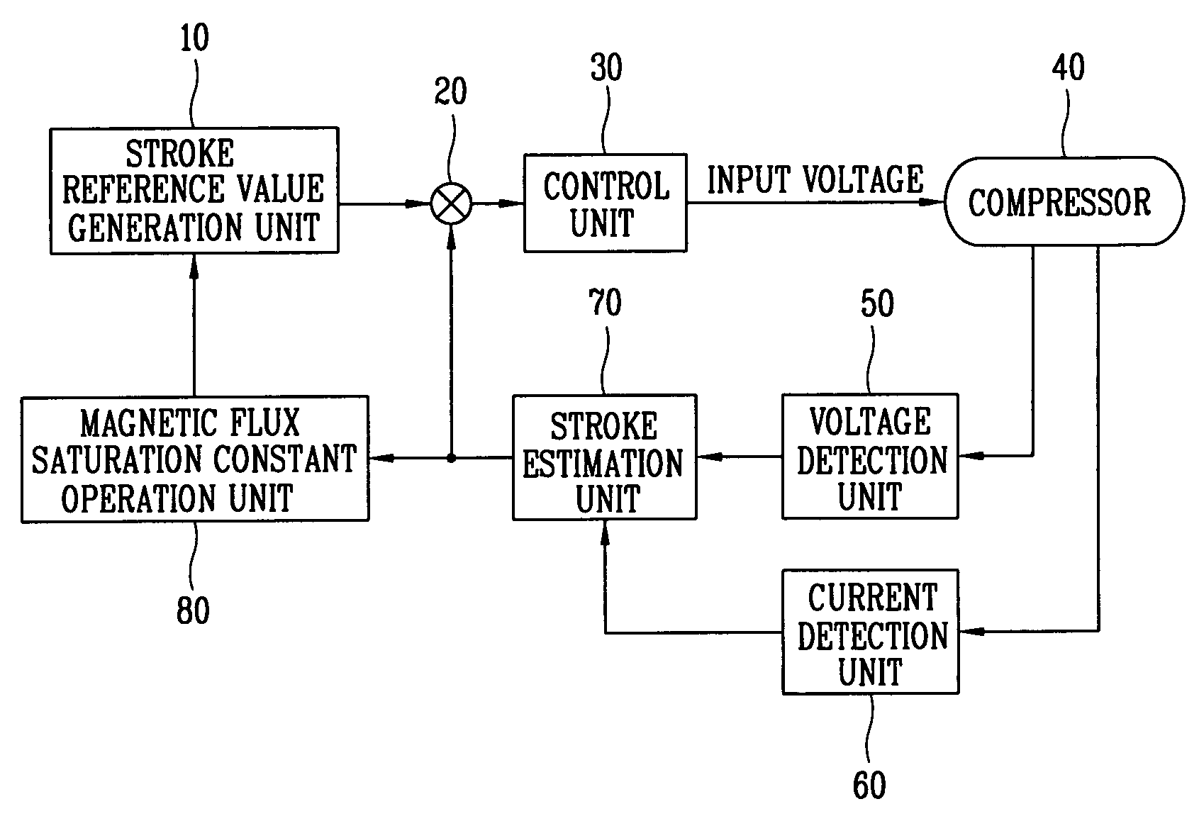
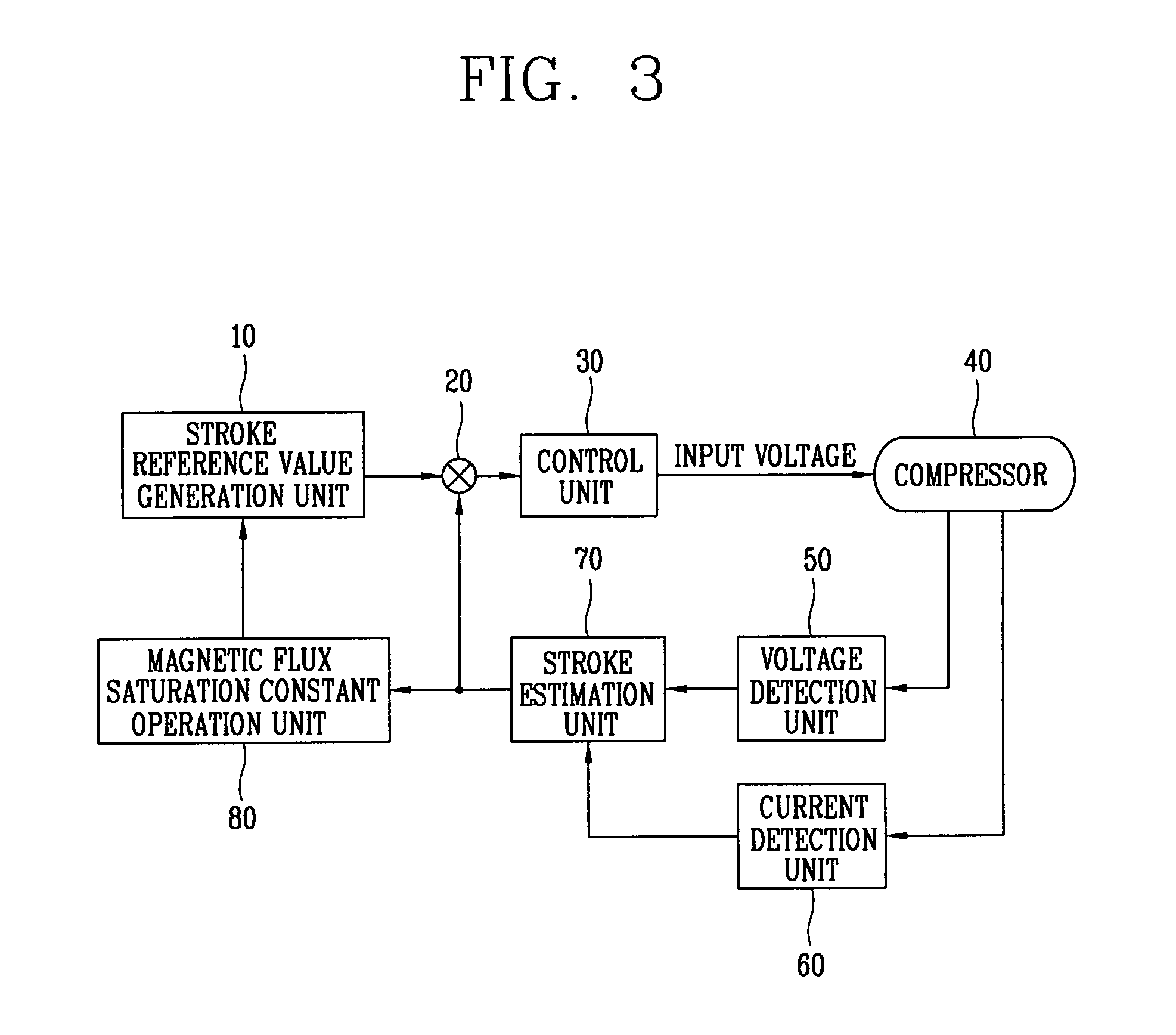
[0036]An apparatus for controlling an operation of a reciprocating compressor and a method therefor which can reduce errors in an operation of a stroke estimated value of the reciprocating compressor, by previously preventing over-saturation of a magnetic flux density generated in a coil of a motor of the reciprocating compressor, by operating a magnetic flux saturation constant of the motor on the basis of the stroke estimated value of the reciprocating compressor and increasing or decreasing a predetermined stroke reference value on the basis of the operated magnetic flux saturation constant will now be described in detail with reference to FIGS. 3 to 5B.

[0037]FIG. 3 is a block diagram illustrating the apparatus for controlling the operation of the reciprocating compressor in accordance with the present invention.

[0038]As ...


PUM


Abstract

The present invention discloses an apparatus for controlling an operation of a reciprocating compressor and a method therefor which can reduce errors in an operation of a stroke estimated value of the reciprocating compressor, by previously preventing over-saturation of a magnetic flux density generated in a coil of a motor. The apparatus for controlling the operation of the reciprocating compressor includes a magnetic flux saturation constant operation unit for operating a magnetic flux saturation constant of a motor of the reciprocating compressor on the basis of a stroke estimated value of the reciprocating compressor, a stroke reference value generation unit for generating an increased or decreased stroke reference value by increasing or decreasing a predetermined stroke reference value on the basis of the magnetic flux saturation constant, and a control unit for controlling a voltage applied to the motor of the reciprocating compressor on the basis of the generated stroke reference value.

Description

[0001]This Nonprovisional application claims priority under 35 U.S.C. § 119(a) on Patent Application No(s). 10-2003-0084642 filed in Korea, Republic of on Nov. 26, 2003, the entire contents of which are hereby incorporated by reference.BACKGROUND OF THE INVENTION[0002]1. Field of the Invention[0003]The present invention relates to a reciprocating compressor, and more particularly to, an apparatus for controlling an operation of a reciprocating compressor, and a method therefor.[0004]2. Description of the Background Art[0005]In general, a reciprocating compressor sucks and compresses a refrigerant gas by linearly reciprocating a piston in a cylinder, and discharges the compressed refrigerant gas. The reciprocating compressor is classified into a recipro method compressor and a linear method compressor according to a method for driving a piston.[0006]In the compressor using the recipro method, a rotary force of a rotary motor is transformed into a reciprocating motion by coupling a cr...

Claims


Application Information

Patent Timeline
Patent Type & Authority Patents(United States)
IPC IPC(8): H02P1/00G05D23/275F04B49/06F04B49/12F04B35/04
CPCF04B35/045F04B2203/0402F04B49/12F04B49/06F04B35/04F04B2203/0401F04B2203/0403F04B2207/046
Inventor YOO, JAE-YOOLEE, CHEL-WOONGKIM, HYUNG-JOO
Owner LG ELECTRONICS INC
Learn More