Composite magnetic head arranged so the reproducing elements do not overlap a pole of a recording element

a technology of reproducing elements and magnetic heads, which is applied in the direction of digital signal error detection/correction, instruments, track selection/addressing details, etc., can solve the problem of enhancing recovery performance and achieve the effect of enhancing the reliability of the reproduction element itsel

Inactive Publication Date: 2007-09-18
HITACHI GLOBAL STORAGE TECH JAPAN LTD
View PDF20 Cites 23 Cited by
  • Summary
  • Abstract
  • Description
  • Claims
  • Application Information

AI Technical Summary

Benefits of technology

[0024]The present invention is achieved by constituting a magnetic disk drive, which uses a composite magnetic head that arranges a plurality of independent reproduction elements correspondent to one recording element, and which reproduces information by properly selecting and using any one of the reproduction elements. Further, the present invention is achieved by constituting a magnetic disk drive, which provides respective magnetically sensitive layers of a plurality of reproduction elements of a composite magnetic head separately so as not to overlap with the normal direction projections of the recording element, thus enabling the composite magnetic head to lessen the influence of a recording magnetic field by the recording element on a magnetically sensitive portion, and which, equipped with this composite magnetic head, reproduces information by selecting and using any one reproduction element from among a plurality of reproduction elements. Furthermore, following shipment, when a malfunction occurs in a reproduction element that is being used from among the plurality of reproduction elements corresponding to one recording element in the composite magnetic head, the magnetic disk drive is provided with a function for selecting and using a remaining reproduction element, which is not being used.

Problems solved by technology

Further, there is no mention of enhancing recovery performance for recovering from a magnetic head malfunction that occurs after a magnetic disk drive has been shipped.

Method used


Image

  • Composite magnetic head arranged so the reproducing elements do not overlap a pole of a recording element
  • Composite magnetic head arranged so the reproducing elements do not overlap a pole of a recording element
  • Composite magnetic head arranged so the reproducing elements do not overlap a pole of a recording element

Examples


Embodiment Construction

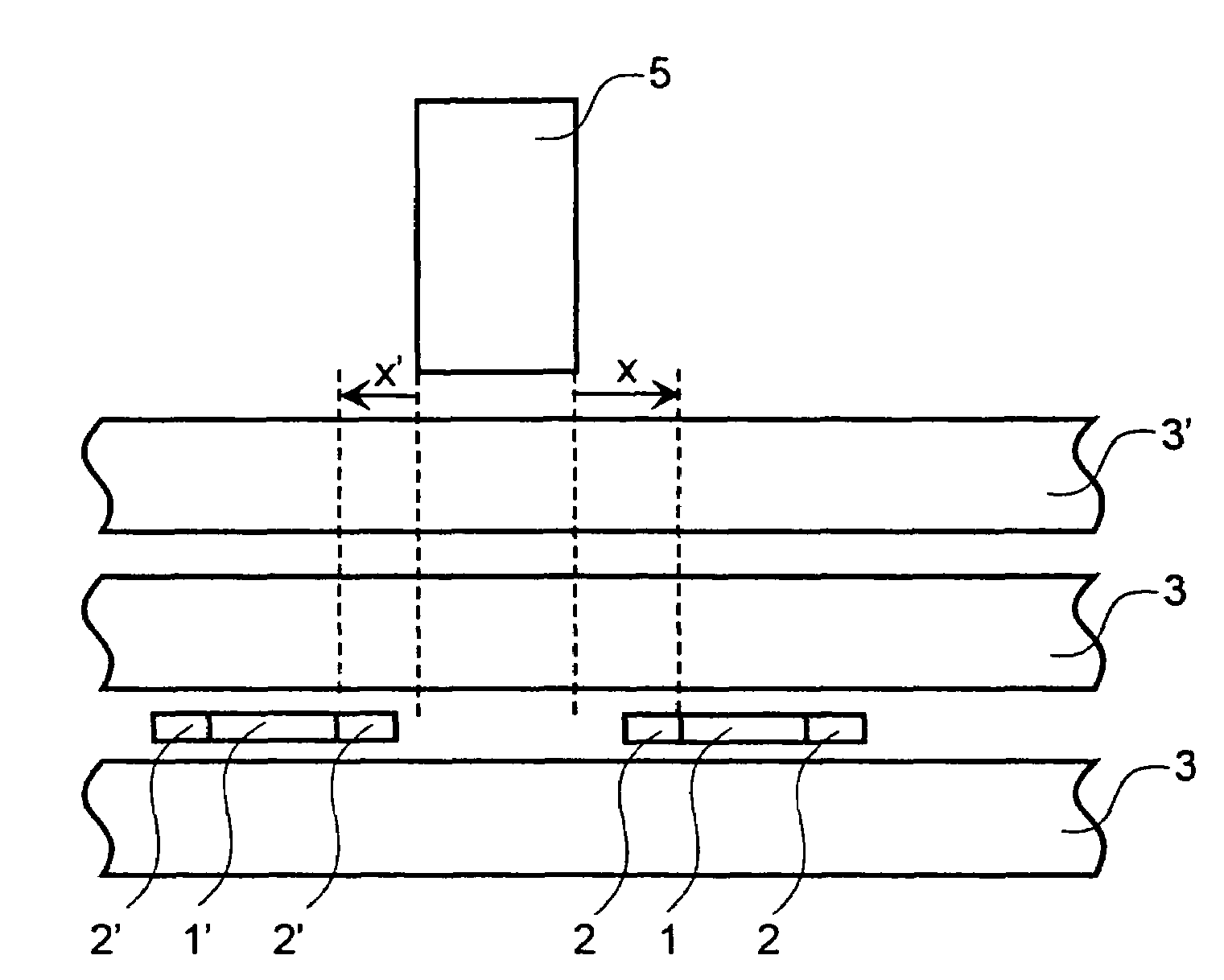
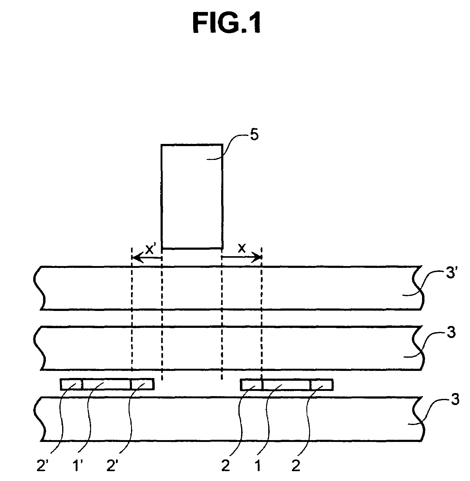
[0036]A first embodiment of the present invention will be explained using FIG. 1. FIG. 1 is a schematic diagram of a composite magnetic head 7 as seen from the side opposite a magnetic disk medium, which is the recording medium therefor. Leakage magnetic field 6 generated from information stored on the recording medium is converted to electrical signals by the composite magnetic head by moving relatively from the bottom to the top of FIG. 1. This composite magnetic head constitutes a structure in which two reproduction element portions and one recording element portion are stacked. A first reproduction element portion has at the least a first magnetically sensitive portion 1 (MR element 1) and first electrode portions 2, which are conductive and make contact with both end portions of this first magnetically sensitive portion 1. To enhance reproduction resolution, two shielding layers 3, which are arranged on both sides of the first reproduction element with gaps therebetween, are ad...


PUM

PropertyMeasurementUnit
thickaaaaaaaaaa
timeaaaaaaaaaa
resistivityaaaaaaaaaa

Abstract

A conventional magnetic head has a structure, in which a MR element and a recording element are stacked. The influence of a recording magnetic field on the magnetically sensitive portion of a reproduction element is lessened and the performance of the MR element is stabilized. Also, the reliability of the magnetic disk drive using a MR element is enhanced. The magnetic disk drive uses a composite magnet head, which has a plurality of reproduction elements arranged such that the magnetically sensitive layer of a reproduction element of the composite magnetic head does not overlap with the normal direction projection of the recording element, and which lessens the influence of a recording magnetic field on the magnetically sensitive portion of each reproduction element.

Description

[0001]This is a continuation application of U.S. Ser. No. 09 / 956,976, filed Sep. 21, 2001 now U.S. Pat. No. 6,816,344.BACKGROUND OF THE INVENTION[0002]1. Field of the Invention[0003]The present invention is related to a way of using a magnetic head in a magnetic disk drive, and more particularly, to a magnetic head, which utilizes a magneto-resistive effect-type electromagnetic conversion element, and a magnetic disk drive for reproducing information using this magnetic head.[0004]2. Description of the Related Art[0005]In recent years, a magneto-resistive effect element (MR element) has been utilized in a magnetic disk drive as an element for reproducing magnetically recorded information. An MR element is one that uses changes in resistivity (magneto-resistive effect) corresponding to leakage magnetic fields from a recording medium, and compared to a conventional inductive-type element, has higher reproduction sensitivity, and is not dependent on circumferential speed. In other word...

Claims


Application Information

Patent Timeline
Patent Type & Authority Patents(United States)
IPC IPC(8): G11B15/12G11B5/09G11B5/00G11B5/012G11B5/02G11B5/265G11B5/29G11B5/31G11B5/39G11B5/48G11B5/49G11B20/18
CPCB82Y10/00B82Y25/00G11B5/012G11B5/2652G11B5/3103G11B5/3909G11B5/3948G11B5/3961G11B5/3967G11B5/488G11B5/4886G11B5/4984G11B20/18G11B5/3945G11B2005/001G11B2005/0016G11B2005/3996G11B2020/183
Inventor TSUCHIYA, REIJIRO
Owner HITACHI GLOBAL STORAGE TECH JAPAN LTD
Why Eureka
Try Eureka