Supercharge Your Innovation With Domain-Expert AI Agents!

Method and systems for improving test of data transmission in multi-channel systems

Inactive Publication Date: 2007-09-18
IBM CORP
View PDF4 Cites 2 Cited by
  • Summary
  • Abstract
  • Description
  • Claims
  • Application Information

AI Technical Summary

Problems solved by technology

This, essentially, because there is no optical memory available yet that would permit storing temporarily the frames of transmitted data while they are examined to determine their final destination.
However, due to the complexity reached by such system, the amount of data used during the communication system test requires huge files and the analysis, generally conducted when the test is completed, takes time.
Furthermore, since the analysis is generally done at the end of the test, information relative to the environment state when an error has occurred may be lost.

Method used


Image

  • Method and systems for improving test of data transmission in multi-channel systems
  • Method and systems for improving test of data transmission in multi-channel systems
  • Method and systems for improving test of data transmission in multi-channel systems

Examples


Embodiment Construction

[0028]The basic principle of the invention consists in adapting the data used for testing the communication system so that the receivers may analyze this data to check its behavior. For sake of clarity, the detail description is based on unicast message however, handling multicast message does not change the method of the invention.

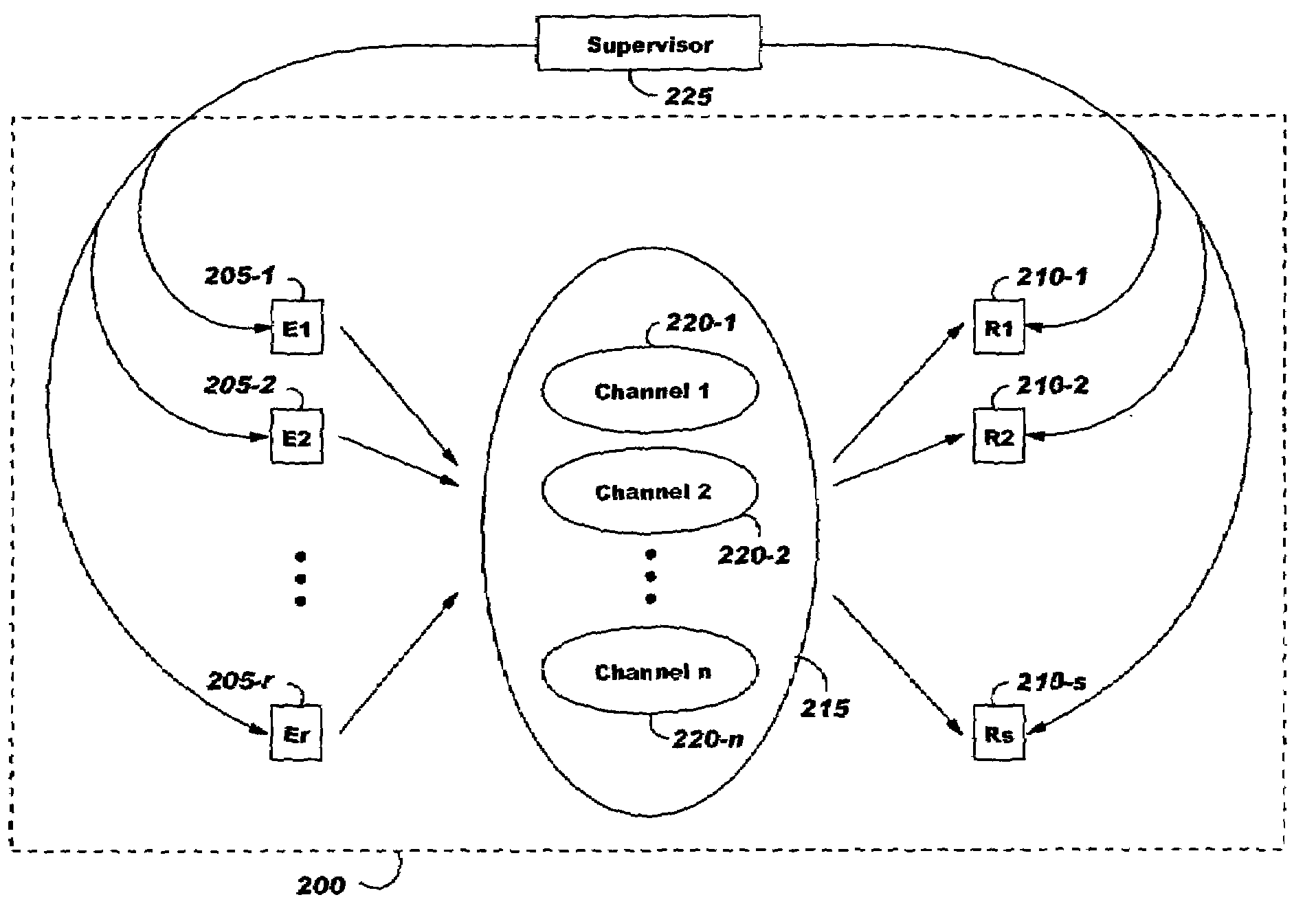
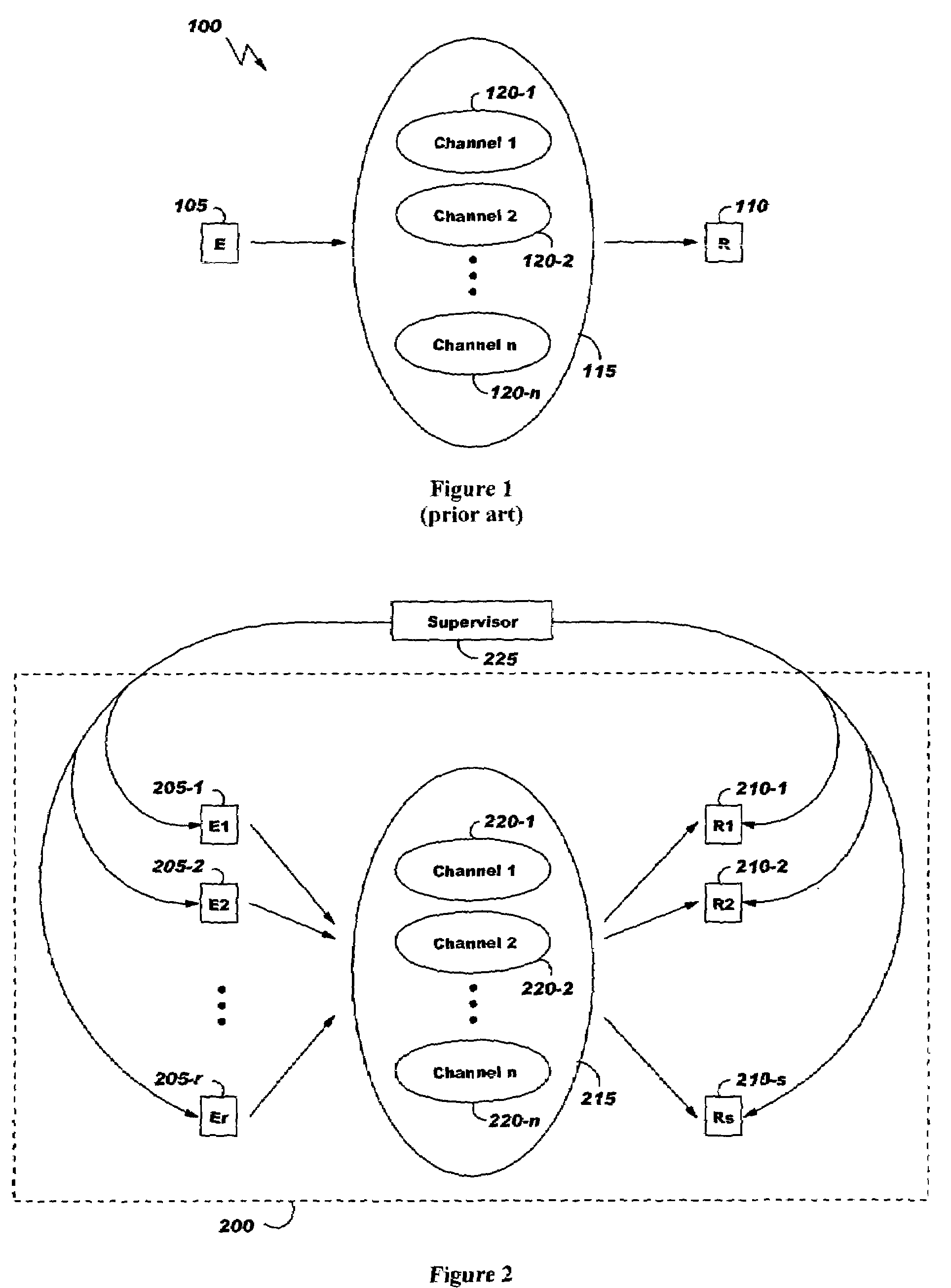
[0029]FIG. 2 illustrates a whole communication system 200 to be tested. Communication system 200 comprises a plurality of emitters 205-1 to 205-r, a plurality of receivers 210-1 to 210-s and a set 215 of channels 220-1 to 220-n adapted to transfer data from any emitter 205-1 to 205-r to any receiver 210-1 to 210-s. One principle of the method of the invention includes transmitting data using all the emitters, receivers and channels and comparing on the fly the data of the receivers with the one of the emitters. To that end, each data used for testing the communication system 200 comprises a connection identifier, generically referred herein below to as CI...


PUM


Abstract

A method and systems to test a communication system (200) comprising a plurality of emitters (205), receivers (210) and channels (220) are disclosed. According to the method of the invention the data used for the test are preprocessed so as to be analyzed on the fly by the receivers during the test. In a preferred embodiment, a connection identifier value characterizing emitter and receiver addresses as well as data properties, if any, is associated to each data and CRC bits are computed to format frames comprising data, connection identifier value and CRC bits (410). During the test, the communication system transmits frames from emitters to corresponding receivers. Upon frames reception, receivers extract data (455), connection identifier value (460) and CRC bits (465) and compute CRC bits on received data (470). The comparison (475) of transmitted and computed CRC bits in receiver allows determining whether or not frames have been well transmitted.

Description

FIELD OF THE INVENTION[0001]The present invention relates to the test of communication systems and more specifically to the test of communication systems comprising a plurality of emitters and receivers and a plurality of channels between each couple of emitter and receiver.BACKGROUND OF THE INVENTION[0002]The rate at which data are transmitted through communication networks has dramatically increased in recent years. Fueled by progresses achieved in fiber and optoelectronic devices and techniques such as DWDM (Dense Wavelength Division Multiplexing), which allow multiplying the bandwidth of a single fiber by merging many wavelengths on it, telecommunications and networking industry had to develop devices capable of routing and switching the resulting huge amount of data that converge and must be dispatched at each network node. Typically, routers and switches situated at those network nodes have to cope with the requirement of having to move data at aggregate rates that must be exp...

Claims


Application Information

Patent Timeline
IPC IPC(8): H03M13/03G06F11/00
CPCH04L43/0823H04L43/10
Inventor BLANC, ALAINMESNET, BRUNOGALLEZOT, RENE
Owner IBM CORP
Features
  • R&D
  • Intellectual Property
  • Life Sciences
  • Materials
  • Tech Scout
  • Unparalleled Data Quality
  • Higher Quality Content
  • 60% Fewer Hallucinations
Learn More