
Piezoelectric device, liquid droplet discharging head using the device, and liquid droplet discharging apparatus using the head

a liquid droplet and device technology, applied in piezoelectric/electrostrictive/magnetostrictive devices, piezoelectric/electrostriction/magnetostriction machines, printing, etc., can solve problems such as insufficient piezoelectric characteristics and poor piezoelectric performance, and achieve high-reliability piezoelectric results

Inactive Publication Date: 2007-09-25
FUJIFILM BUSINESS INNOVATION CORP
View PDF9 Cites 2 Cited by
  • Summary
  • Abstract
  • Description
  • Claims
  • Application Information

AI Technical Summary

Benefits of technology

The present invention provides a piezoelectric device that can maintain its piezoelectric characteristics even after extended use in high-temperature, high-humidity environments. The invention solves the problem of deterioration of the piezoelectric device caused by environmental factors such as electrochemical reactions and oxygen holes. The invention provides a piezoelectric device with a layer that can eliminate oxygen holes and prevent deterioration of the piezoelectric characteristics. The invention also provides a liquid droplet discharge head and a liquid droplet discharge apparatus that use the piezoelectric device described above.

Problems solved by technology

Further, it has been confirmed that even with a structure in which a conductive metal oxide is formed at a positive potential application side (the higher potential application side) as in JP-A No. 2001-88296, as described earlier, environmental resistance, particularly to high temperatures and high humidities, may not be sufficient and piezoelectric characteristics may deteriorate.

Method used

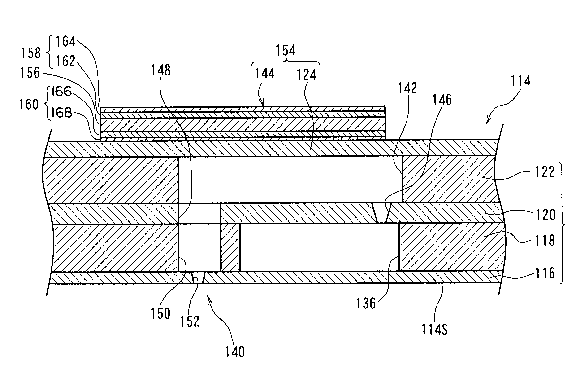
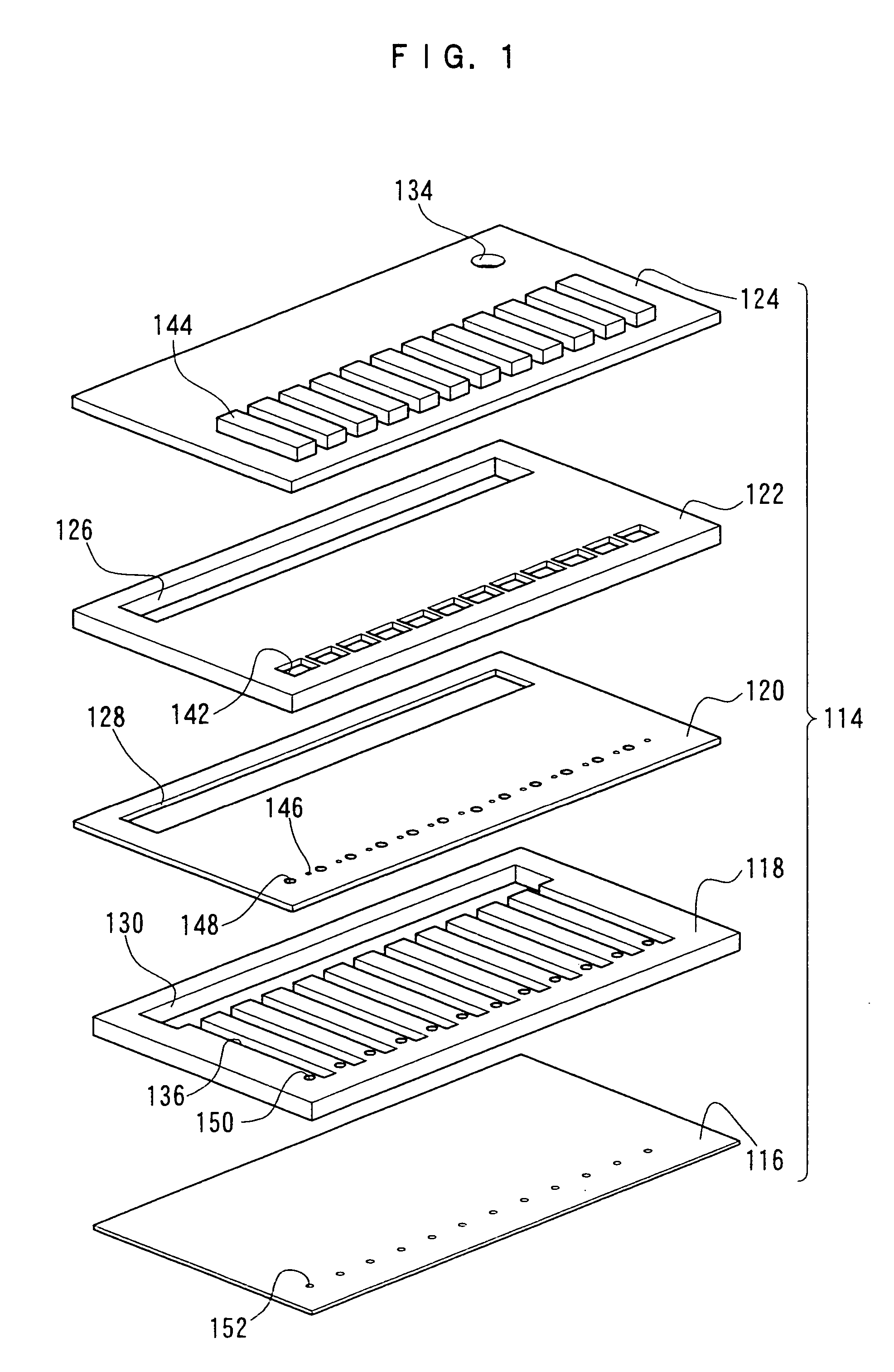
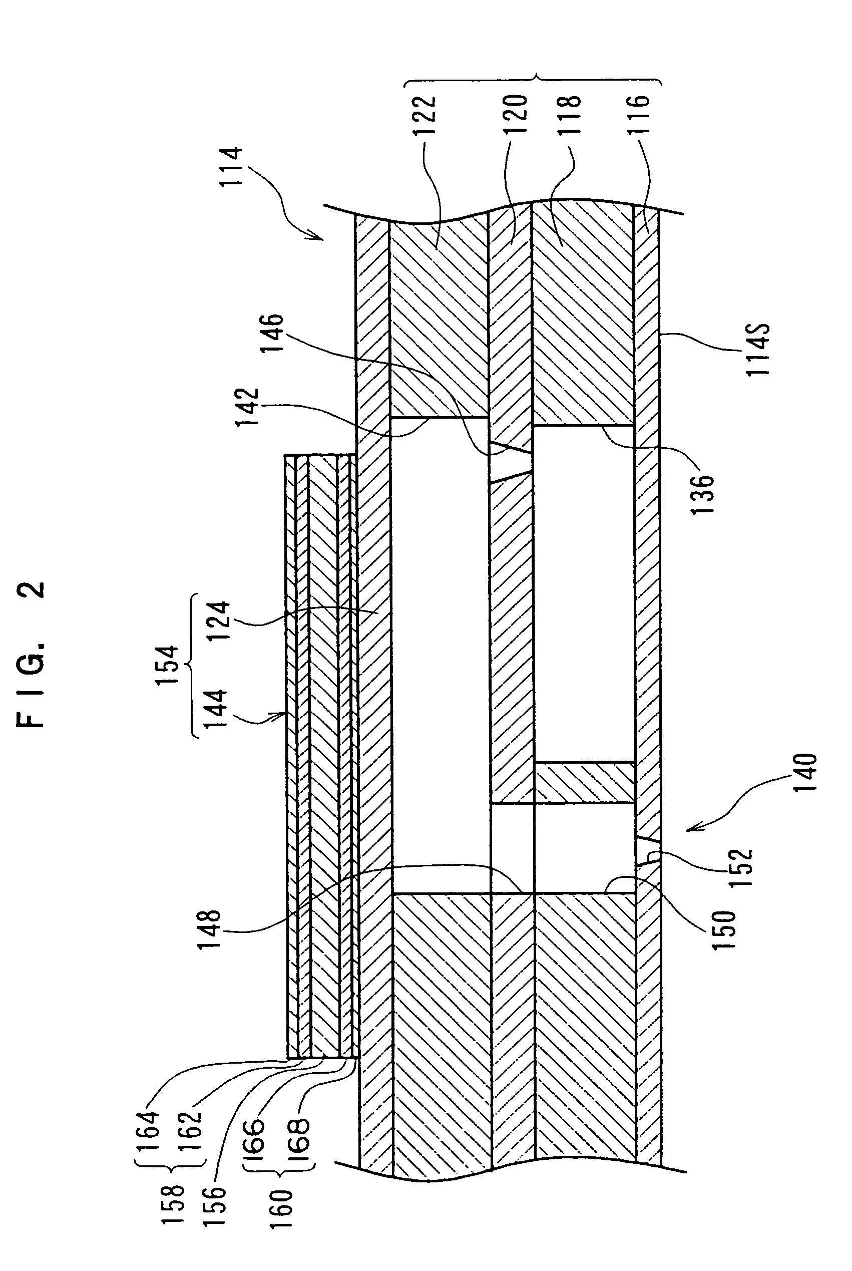

Image

  • Piezoelectric device, liquid droplet discharging head using the device, and liquid droplet discharging apparatus using the head
  • Piezoelectric device, liquid droplet discharging head using the device, and liquid droplet discharging apparatus using the head
  • Piezoelectric device, liquid droplet discharging head using the device, and liquid droplet discharging apparatus using the head

Examples


example 1

[0147]

[0148]First, a tin oxide layer of 0.2 μm thickness was formed, by reactive sputtering using a tin target, at one face of a plate of PZT with thickness 30 μm. The formation of this tin oxide layer was carried out in conditions in which a flow rate of Ar gas was 20 cm3 / min, a flow rate of O2 gas was 5 cm3 / min, and total pressure was 4×10⁻³ Pa, with 100 W of electrical power being applied to the tin target (3 inches).

[0149]Then, because this tin oxide layer was non-conductive, a Ni layer of 0.6 μm thickness and a Au layer of 0.2 μm thickness were formed on the tin oxide by successive sputtering processes. The Ni layer was formed using a Ni target and the Au layer was formed using a Au target.

[0150]Next, a Au layer of 0.2 μm thickness was formed, by sputtering using a Au target, at the other face of the PZT plate. The formation of this Au layer was carried out in conditions in which a flow rate of Ar gas was 25 cm3 / min and total pressure was 4×10⁻³ Pa, with 100 W of electrical pow...


PUM


Abstract

A piezoelectric device includes a piezoelectric body layer, a first electrode layer at one face side of the piezoelectric body layer, and a second electrode layer at a side of a face of the same that is opposite to the side at which the first electrode layer is disposed. Higher potentials are applied to the first electrode layer and lower potentials are applied to the second electrode layer. The piezoelectric device features a metallic layer disposed in contact with a piezoelectric body layer surface at the side at which the first electrode layer is provided, and a metal oxide layer disposed in contact with a piezoelectric body layer surface at the side at which the second electrode layer is provided. The metallic layer is formed of a metallic material with a standard electrode potential greater than 0 V, and the metal oxide layer is formed of a metal oxide.

Description

CROSS-REFERENCE TO RELATED APPLICATION[0001]This application claims priority under 35 USC 119 from Japanese Patent Application No. 2003-195741, the disclosure of which is incorporated by reference herein.BACKGROUND OF THE INVENTION[0002]1. Field of the Invention[0003]The present invention relates to a piezoelectric device, a liquid droplet discharging head which uses the device, and a liquid droplet discharging apparatus which uses the liquid droplet discharging head. The present invention more particularly relates to a piezoelectric device for discharging liquid droplets to record text, images and the like on recording media and / or for implementing formation of fine-detail patterns and thin films and the like on substrates, and to a liquid droplet discharging head which uses this device and a liquid droplet discharging apparatus which uses the liquid droplet discharging head.[0004]2. Description of the Related Art[0005]A liquid droplet discharging head which uses pressure-generatin...

Claims


Application Information

Patent Timeline
Patent Type & Authority Patents(United States)
IPC IPC(8): B41J2/045B41J2/055B41J2/135B41J2/14H01L41/047H01L41/09H01L41/187H01L41/22H01L41/29H02N2/00
CPCB41J2/14233H01L41/047B41J2202/03H01L41/0973H10N30/878H10N30/877H10N30/2047
Inventor YAGI, TAKASHISETO, SHINJI
Owner FUJIFILM BUSINESS INNOVATION CORP
Learn More