Piezoelectric device and method for using same
a piezoelectric device and piezoelectric technology, applied in piezoelectric/electrostrictive/magnetostrictive devices, piezoelectric/electrostrictive/magnetostriction machines, piezoelectric/electrostrictive/magnetostriction devices, etc., can solve the problem of unintentional application of electric field in reverse polarization direction, depolarization of nb-doped pzt film, etc. problem
- Summary
- Abstract
- Description
- Claims
- Application Information
AI Technical Summary
Benefits of technology
Problems solved by technology
Method used
Image
Examples
modification example 1
CONCERNING DEVICE STRUCTURE
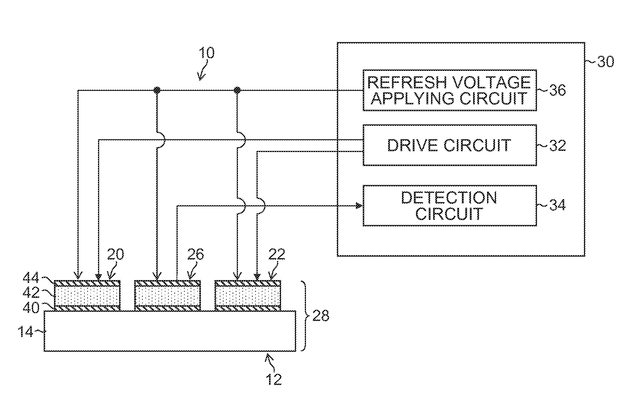
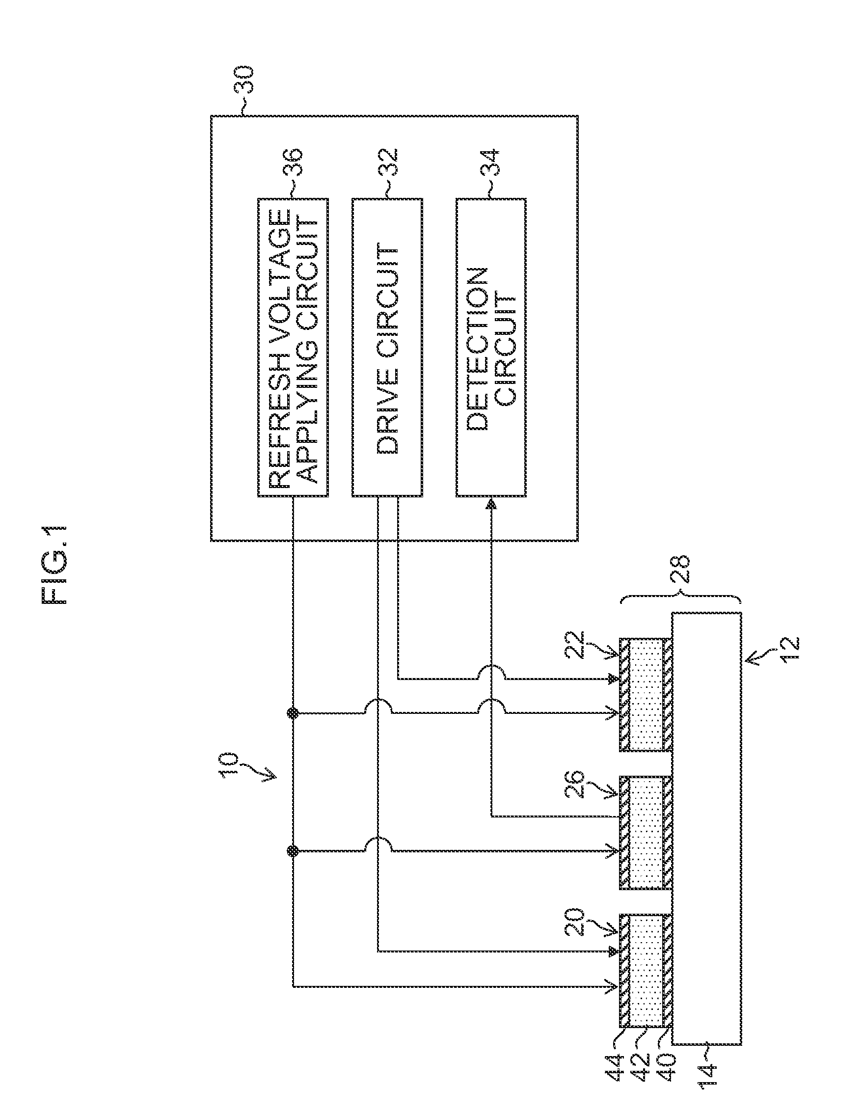
[0063]FIG. 1 illustrates a form where the respective piezoelectric elements 20, 22, and 26 are individually isolatedly-processed in element units showing the structure of the lower electrode 40, the piezoelectric body film 42, and the upper electrode 44 being isolated in element units, but a form may be used in which the lower electrode 40 and the piezoelectric body film 42 are not individually isolatedly-processed for each element. For example, a lower electrode can be common in the plural piezoelectric elements 20, 22, and 26 illustrated in FIG. 1 (non-patterned common electrode layer). The piezoelectric body film 42 may be also constituted as a one body piezoelectric body film not individually isolatedly-processed for the plural piezoelectric elements 20, 22, and 26 (e.g., see FIG. 1 and FIG. 3 in PTL 2). Patterning (isolatedly forming) the upper electrode 44 corresponding to the piezoelectric elements 20, 22, and 26 makes portion of the piezoelectric b...
modification example 2
CONCERNING DEVICE STRUCTURE
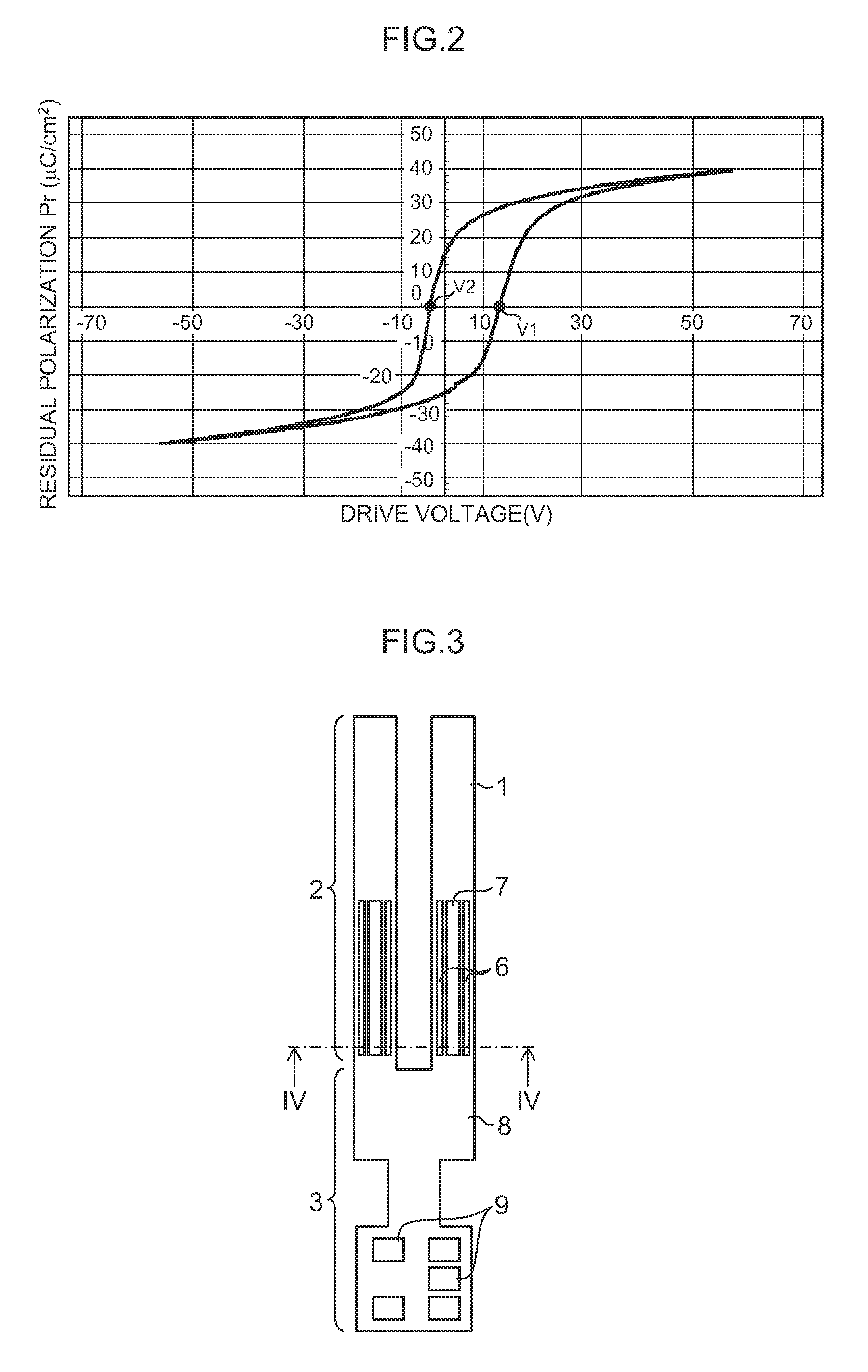
[0064]FIG. 1 illustrates the structure in which two the piezoelectric elements for drive 20 and 22 and one piezoelectric element for detection 26 are combined as the sensor element unit 28, but the number of the piezoelectric elements, whether or not the elements for drive and for detection are combined, a ratio of the numbers of those combined, and an arrangement of the piezoelectric elements are not limited to this example, and various designs may be made depending on purposes or specifications of the device. For example, a tuning fork-shaped gyro sensor (FIG. 3 and FIG. 4) described later includes the plural vibrating parts 12 having the structure illustrated in FIG. 1. A form may be used in which an electrode for drive is arranged in a center portion and electrodes for detection are arranged on both sides thereof, like the gyro sensor described in PTL 2.
[0065]The above modifications can be applied to various piezoelectric devices regardless of the stru...
experiment 1
(Preliminary Experiment 1)
[0089]For examining a polarization degree of the produced gyro sensor, the relevant produced device, with no initial polarization treatment made, was driven by applying a drive voltage of 0.14V to the drive electrode 6 while detecting an output voltage acquired from the detection electrode 7. With a voltage (refresh voltage) applied to the detection electrode being changed, the voltages output were plotted and normalized with an output at the electric field intensity of −20V (−100 kV / cm) as “1”.
[0090]A point expressed by a black square in FIG. 5 illustrates a plotted point of the polarization degree after normalization. From the result of the preliminary experiment 1, it was found out that the piezoelectric body film in this example is almost polarized with no polarization treatment being made (in a no polarization treatment state) (polarization is roughly uniformed in an initial state). In other words, use of the piezoelectric material like this eliminates...
PUM
 Abstract
Description
Claims
Application Information
 - R&D
- Intellectual Property
- Life Sciences
- Materials
- Tech Scout
- Unparalleled Data Quality
- Higher Quality Content
- 60% Fewer Hallucinations
Browse by: Latest US Patents, China's latest patents, Technical Efficacy Thesaurus, Application Domain, Technology Topic, Popular Technical Reports.
© 2025 PatSnap. All rights reserved.Legal|Privacy policy|Modern Slavery Act Transparency Statement|Sitemap|About US| Contact US: help@patsnap.com


