Fan impeller
a technology of fan and impeller, which is applied in the direction of non-positive displacement fluid engines, radial flow pumps, pump components, etc., can solve the problems of reducing the performance and lifetime of electronic devices, generating large amounts of waste heat during operation, and damage to internal components, so as to achieve the effect of maintaining operation performance and strengthening the structur
- Summary
- Abstract
- Description
- Claims
- Application Information
AI Technical Summary
Benefits of technology
Problems solved by technology
Method used
Image
Examples
first embodiment
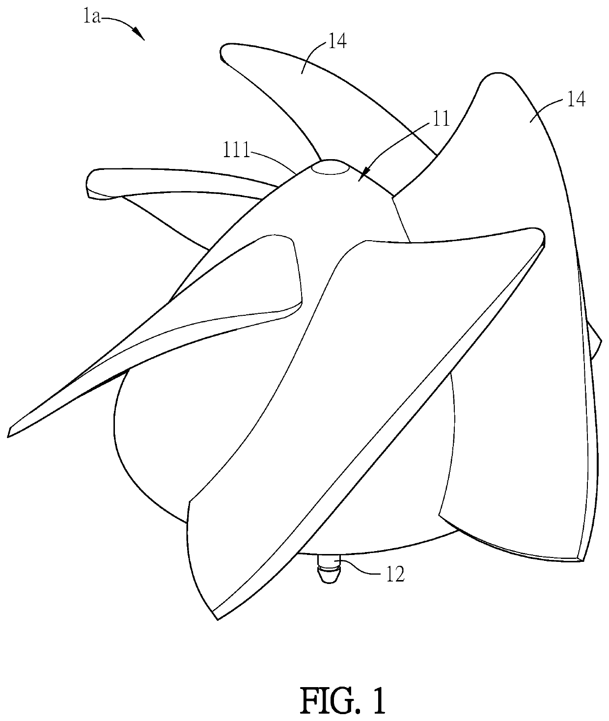
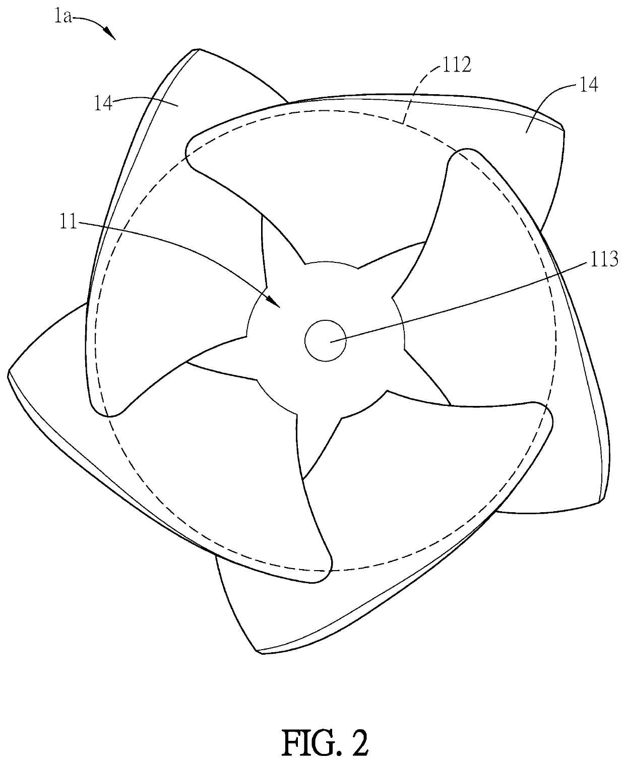
[0035]FIGS. 1 and 2 are a schematic diagram and a top view of a fan impeller according to this disclosure. As shown in FIGS. 1 and 2 the fan impeller 1a comprises a hub 11, a shaft 12, and a plurality of blades 14 disposed around the hub 11. The hub 11 has a curved surface 111, and the blades 14 substantially extend outwardly from the curved surface 111. Referring to FIG. 2, the hub 11 forms a projection area. The center of the projection area is a top portion 113 of the hub 11, and the edge of the projection area is a bottom portion 112 of the hub 12. The blades 14 also form corresponding projection areas. The projection areas of the blades 14 are partially overlapped with that of the hub 11.
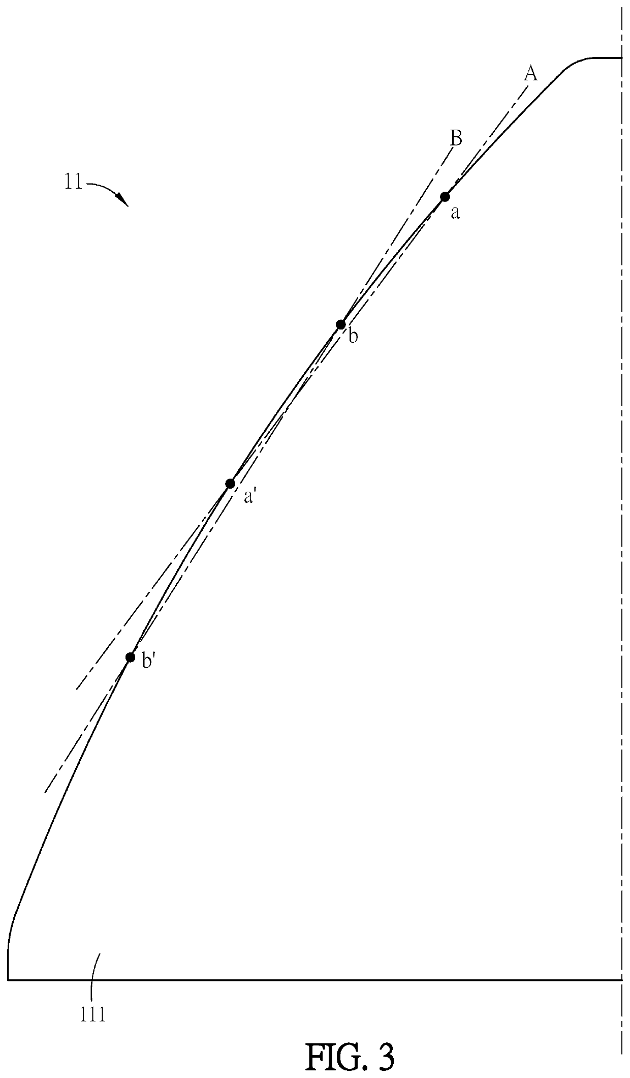
[0036]FIG. 3 is a schematic diagram showing the outer periphery of the hub 11 of the fan impeller 1a according to the first embodiment of this disclosure. The feature of the curved surface 111 on the outer periphery of the hub 11 of the fan impeller 1a will be described hereinafter with referen...
second embodiment
[0043]FIG. 5 is a sectional view of a fan impeller 1b according to this disclosure. The structure of the fan impeller 1b as shown in FIG. 5 is mostly the same as that shown in FIG. 4. Different from the embodiment of FIG. 4, as shown in FIG. 5, the metal housing 13b and the magnetic ring 133b are aligned with the extension portion 114.
[0044]FIG. 6 is a bottom view of the fan impeller 1b according to the second embodiment of this disclosure. Referring to FIGS. 5 and 6, in the fan impeller 1b of this embodiment, a plurality of spacers f are formed between the bottom portion 112 and the extension portion 114 of the hub 11, and any two adjacent spacers f form an accommodating space s therebetween. In general, the fan impeller 1b of this embodiment is usually applied to the high speed fan, which has the rotation speed of 10,000 RPM or higher. The accommodating space s can be used to fill the balance material (e.g. clay) for calibrating the weight balance of the fan impeller 1b. This conf...
PUM
 Abstract
Description
Claims
Application Information
 - R&D
- Intellectual Property
- Life Sciences
- Materials
- Tech Scout
- Unparalleled Data Quality
- Higher Quality Content
- 60% Fewer Hallucinations
Browse by: Latest US Patents, China's latest patents, Technical Efficacy Thesaurus, Application Domain, Technology Topic, Popular Technical Reports.
© 2025 PatSnap. All rights reserved.Legal|Privacy policy|Modern Slavery Act Transparency Statement|Sitemap|About US| Contact US: help@patsnap.com


