Piezoelectric element, liquid jetting head, and method for manufacturing thereof

a liquid jetting head and piezoelectric technology, applied in piezoelectric/electrostrictive transducers, conductive pattern formation, transducer types, etc., can solve the problems of undesirable excessive interdiffusion in the bottom electrode, and achieve high piezoelectric characteristics, high piezoelectric reliability, and good reproducibility

Active Publication Date: 2005-04-14
SEIKO EPSON CORP
View PDF6 Cites 3 Cited by
  • Summary
  • Abstract
  • Description
  • Claims
  • Application Information

AI Technical Summary

Benefits of technology

[0015] An object of the present invention is to provide a piezoelectric element having consistently high piezoelectric characteristics, and to provide a method for manufacturing a liquid jetting head in which this element is used, by stabilizing and obtaining with good reproducibility a degree of orientation that is suitable for a piezoelectric thin film. Another object is to provide a highly reliable piezoelectric element in which the in-film stress of the piezoelectric material film and bottom electrode is reduced, and to provide a liquid jetting head in which this element is used.
[0016] Yet another object is to provide a method capable of yielding a piezoelectric thin film whose composition is uniform in the film thickness direction, and of reducing the in-film stress; to provide a piezoelectric element endowed with good piezoelectric characteristics and reliability; and to provide a liquid jetting head in which this element is used.
[0017] According to a method for manufacturing a piezoelectric element in accordance with the present invention, a Ti film is formed on a layered bottom electrode, a piezoelectric material layers are then formed in a plurality of cycles of layer formation to produce a PZT piezoelectric thin film predominantly oriented in the 100 plane, and a top electrode is formed on the piezoelectric thin film. When the piezoelectric material layers are formed in a plurality of cycles, the annealing temperature of the initial cycle of layer formation is set higher than the annealing temperature of the other cycles of layer formation. The electromechanical conversion functionality of the piezoelectric element is excellent in the case of a piezoelectric thin film predominantly oriented in the 100 plane. The piezoelectric material layer formed during the initial cycle greatly affects the subsequently layered piezoelectric material layers.
[0019] The method for manufacturing a piezoelectric element in accordance with the present invention can provide the same effects as above by making the annealing time during the initial cycle of layer formation longer than the annealing time during the other cycles of layer formation when a piezoelectric material layers are formed.

Problems solved by technology

However, excessively promoting interdiffusion in the bottom electrode is undesirable because of insufficient adhesiveness and other problems.

Method used


Image

  • Piezoelectric element, liquid jetting head, and method for manufacturing thereof
  • Piezoelectric element, liquid jetting head, and method for manufacturing thereof
  • Piezoelectric element, liquid jetting head, and method for manufacturing thereof

Examples


first embodiment

5. Manufacturing Method

[0065] A method for manufacturing a piezoelectric element in accordance with the present invention will now be described. FIGS. 4 and 5 are cross-sectional schematic views depicting the method for manufacturing a piezoelectric element and an inkjet recording head in accordance with an embodiment of the present invention.

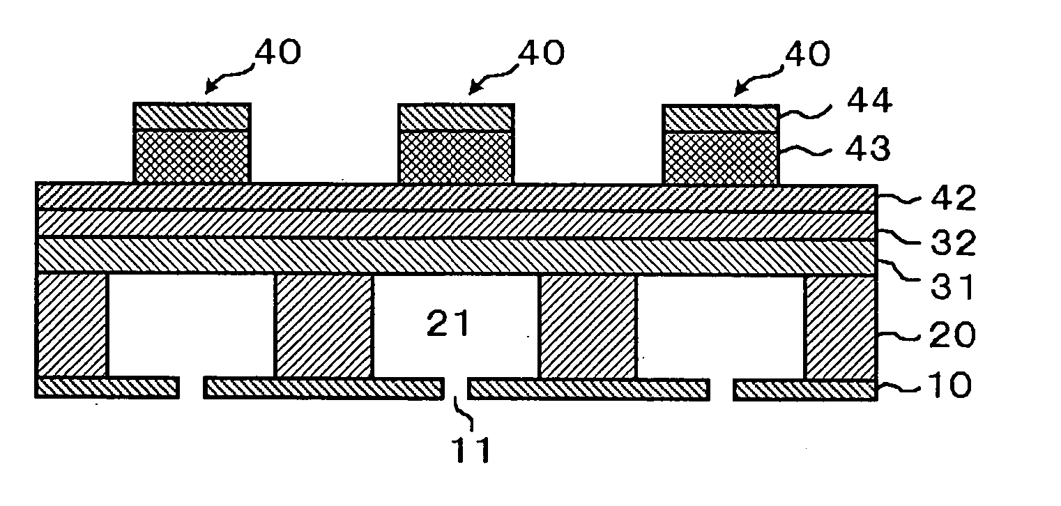
[0066] Oxide Film Formation Step (S1)

[0067] It is a step in which a silicon substrate constituting a pressure chamber substrate 20 is heat-treated in an oxidizing atmosphere containing oxygen or water vapor to form an oxide film 31 composed of silicon oxide (SiO2). In this step, CVD may also be used in stead of the commonly used thermal oxidation.

[0068] Step for Forming ZrO2 Film (S2)

[0069] It is a step in which a ZrO2 film 32 is formed on the oxide film 31, which is itself formed on one side of the pressure chamber substrate 20. The ZrO2 film 32 is obtained by a process forming a Zr layer by sputtering or vacuum vapor deposition and heat-t...

second embodiment

6. Manufacturing Method

[0099] The manufacturing method according to the second embodiment differs from the first embodiment in terms of the annealing conditions established in the step (S6) for annealing the precursor film, with the other elements being the same as in the manufacturing method according to the first embodiment.

[0100] Although in the first embodiment the annealing temperature of the first cycle was set higher than the annealing temperature of the other cycles, it was learned that a highly reliable piezoelectric thin film could also be obtained when the annealing temperature was kept the same for each layer. In particular, in a piezoelectric thin film, the degree of orientation in the (100) plane on a portion adjacent to the top electrode was higher than the degree of orientation in the (100) plane on a portion adjacent to the bottom electrode. It was obtained by repeating the combination of the step of forming a piezoelectric precursor film and the step of performing...

third embodiment

8. Manufacturing Method

[0107] The manufacturing method of the third embodiment is the same as the manufacturing method of the first embodiment except that a sol-gel technique in which the sol used has a different composition than in the first embodiment is employed in the step (S5) for forming the piezoelectric precursor film.

[0108] In the step in which a piezoelectric material layer composed of PZT is formed a plurality of times to produce a piezoelectric thin film in accordance with the third embodiment, the Zr / Ti ratio of the sol in the first layer of the two-layer piezoelectric precursor film applied in the first film formation cycle is made higher than the Zr / Ti ratio of the sol in the second layer or of the sol in the piezoelectric precursor applied in the other film formation cycles. For example, the Zr / Ti ratio of the sol in the first layer is set to 58 / 42, and the Zr / Ti ratio of the sol in the remaining layers is set to 55 / 45 when the sol in the first layer is applied in a...


PUM

PropertyMeasurementUnit
thicknessaaaaaaaaaa
thicknessaaaaaaaaaa
thicknessaaaaaaaaaa

Abstract

The present invention provides a piezoelectric element having consistently high piezoelectric characteristics, and a method for manufacturing a liquid jetting head in which this element is used, by obtaining a degree of orientation that is suitable for a piezoelectric thin film, stably and with good reproducibility. A Ti film is formed on a layered bottom electrode 42, piezoelectric material layers constituting a piezoelectric thin film 43 is formed a plurality of cycles of layer formation, and a top electrode 44 is formed on the piezoelectric thin film 43 to produce a piezoelectric element 40. When the piezoelectric material layers are formed, the annealing temperature of the first cycle of layer formation is set higher than the annealing temperature of the other cycles of layer formation. In addition, the annealing time of the first cycle of layer formation is made longer than the annealing time of the other cycles of layer formation. The degree of orientation in the 100 plane is thereby increased, and the bottom electrode can be prevented from undergoing oxidation or Pd diffusion.

Description

CROSS-REFERENCE TO RELATED APPLICATIONS [0001] Not applicable. STATEMENT REGARDING FEDERALLY-SPONSORED RESEARCH AND DEVELOPMENT [0002] Not applicable. REFERENCE TO MICROFICHE APPENDIX / SEQUENCE LISTING / TABLE / COMPUTER PROGRAM LISTING APPENDIX [0003] (Submitted on a Compact Disc and an Incorporation-by-Reference of the Material on the Compact Disc) [0004] Not applicable. BACKGROUND OF THE INVENTION [0005] 1. Field of the Invention [0006] The present invention relates to a piezoelectric element having electromechanical conversion functionality, a liquid jetting head featuring this piezoelectric element, and a method for manufacturing these. More particularly, the invention relates to a piezoelectric element that has excellent piezoelectric characteristics when used in a liquid jetting head, to a liquid jetting head featuring this, and to a method for manufacturing these. [0007] 2. Related Art [0008] Inkjet recording heads and other liquid jetting heads use piezoelectric elements as driv...

Claims


Application Information

Patent Timeline
Patent Type & Authority Applications(United States)
IPC IPC(8): B05B17/04B41J2/045B41J2/055B41J2/135B41J2/14B41J2/16H01L21/28H01L41/08H01L41/09H01L41/187H01L41/22H01L41/318H01L41/319H01L41/39H01L41/43
CPCB41J2/14233B41J2/161B41J2/1628B41J2/1642B41J2/1645Y10T29/49155B41J2002/14491H01L41/1876H01L41/318H01L41/319Y10T29/42B41J2/1646H10N30/8554H10N30/079H10N30/078
Inventor MURAI, MASAMILI, XIN-SHAN
Owner SEIKO EPSON CORP
Why Eureka
Try Eureka