Control unit for mixed light illumination, especially for microscopy

a control unit and light technology, applied in the field of mixed light illumination control units, can solve the problems of insufficient illumination systems for many applications, fiber optic illumination systems can control individual segments of lighting units only with considerable mechanical effort and expense, and reduce the brightness and compact structure of led illumination heads, etc., to achieve a simple and rapid manner for users.

Inactive Publication Date: 2007-09-25
SCHOTT AG +1
View PDF4 Cites 72 Cited by
  • Summary
  • Abstract
  • Description
  • Claims
  • Application Information

AI Technical Summary

Benefits of technology

[0014]It is an object of the present invention to provide an economical control unit, which permits mixed light observation of the above-described type with a microscope in a simple and rapid manner for the user or operator.

Problems solved by technology

However reduced brightness and less compact structure for the LED illumination heads are substantial disadvantages for the LED illumination systems in contrast to the fiber optic illumination systems.
Fiber optic illumination systems can control individual segments of lighting units only with considerable mechanical effort and expense.
It has been shown that the known illumination systems for many application purposes are insufficient.
When the same object must be observed still later, often time consuming new adjustments of the illumination conditions must be performed.
Their reproducibility is problematical, time consuming and often depends on the cleverness of the user.
Furthermore currently each lighting or illumination device in these combinations of illumination systems has its own current and / or control unit, so that the total system takes up a comparatively large amount of space and is expensive.

Method used


Image

  • Control unit for mixed light illumination, especially for microscopy
  • Control unit for mixed light illumination, especially for microscopy
  • Control unit for mixed light illumination, especially for microscopy

Examples


Embodiment Construction

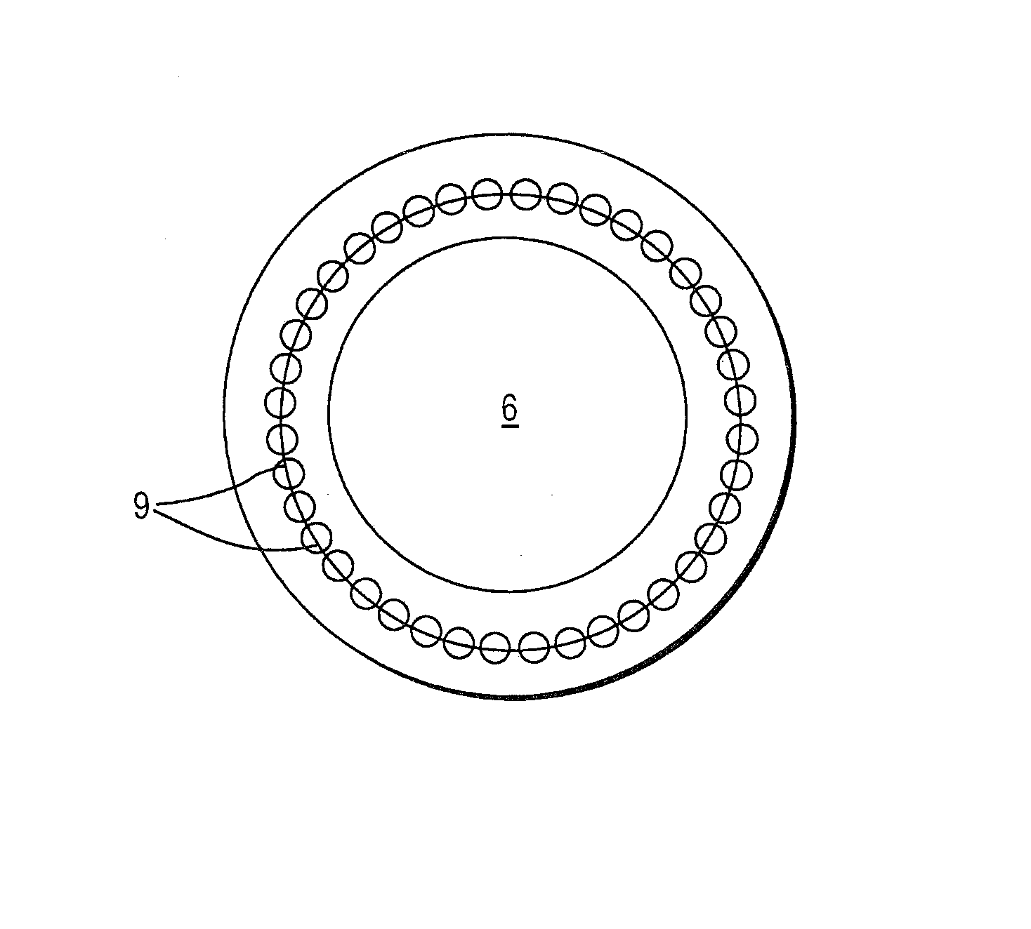
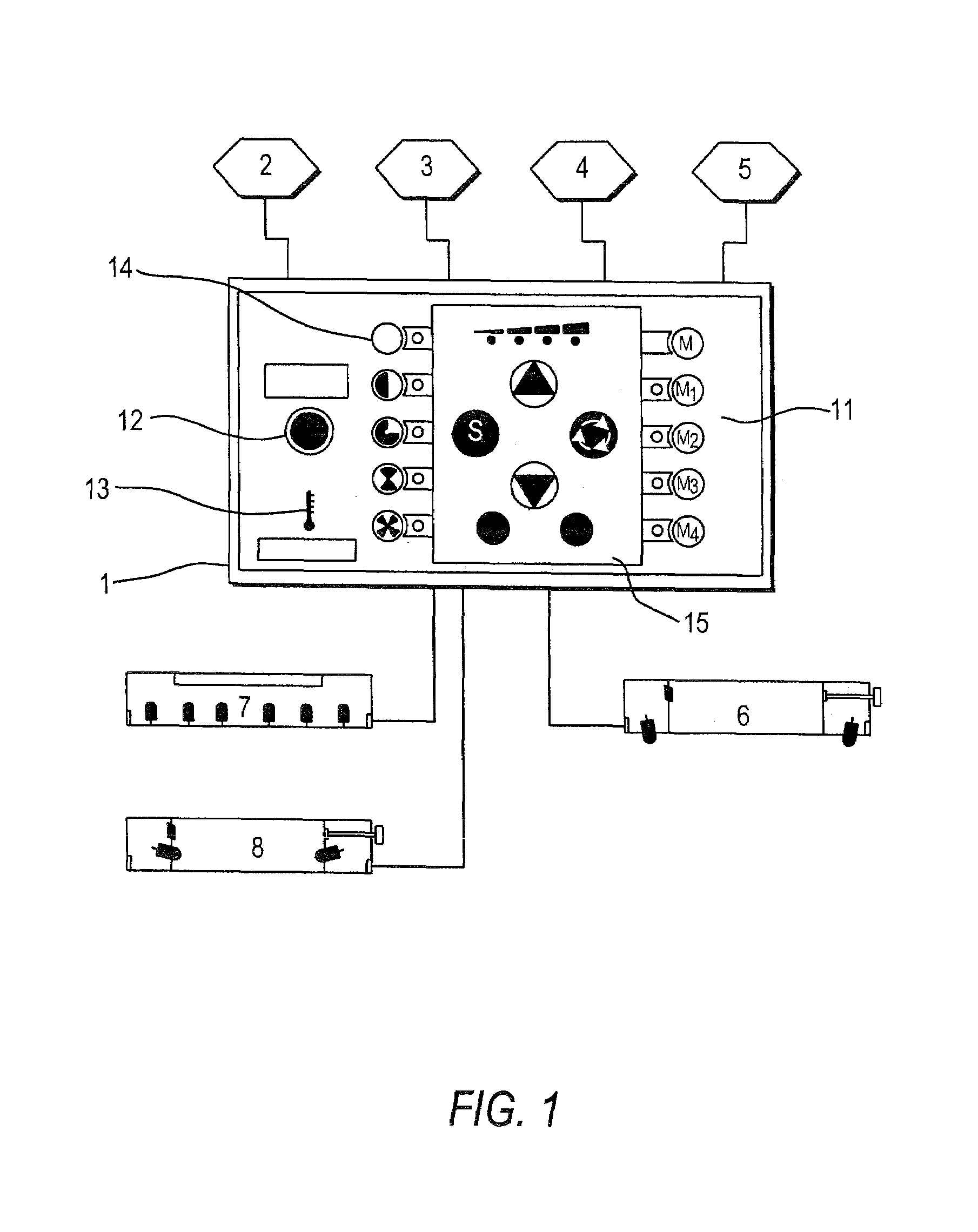
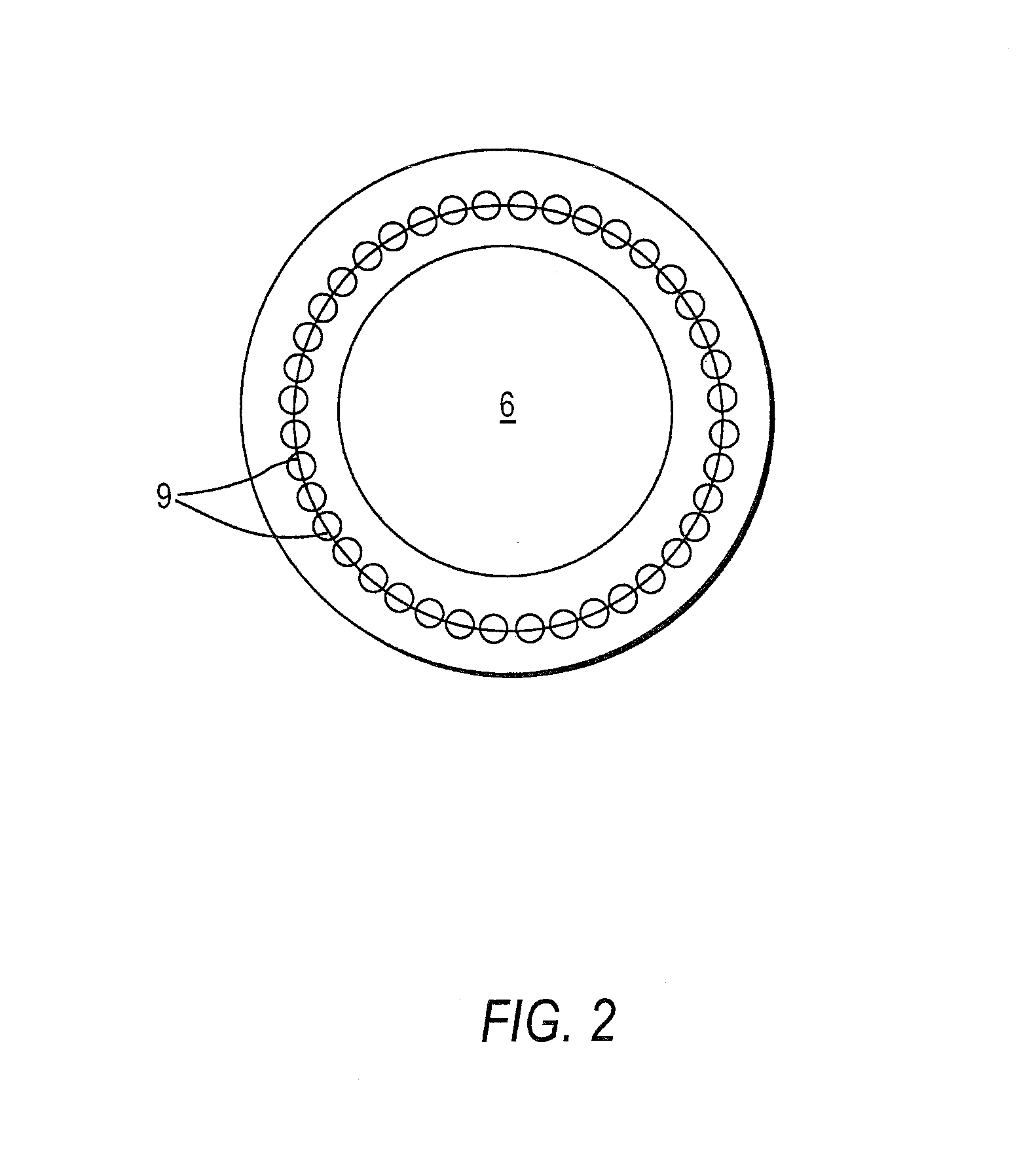
[0030]The control unit 1 shown in FIG. 1 has an interface 2 for connection to an external network, flash synchronization means 3 for connection to an external image-taking unit, a foot switch 4 for retrieval and switching between different user settings or commands and an interface 5 for connection with an external computer. An LED incident light brightness field ring light 6, an LED incident light dark field ring light 8 and an LED transmitted light 7 are connected to the control unit 1 and act as the lighting units of the invention, which are controlled by the control unit 1. The plan view of ring light 6 shown in FIG. 2 shows the circular arrangement of the individual LEDs 9.

[0031]Different mixed light states can be produced by suitable control of the lighting units 6, 7 and 8 by the control unit 1. In order to maintain a definite mixed light state the user must retrieve or call up generally its user commands or data for each of the connected lighting units and / or the predetermin...


PUM


Abstract

A control unit for a microscope, a stereomicroscope, or an industrial image processing machine is described, to which at least three lighting units, e.g. for incident light-bright field illumination, incident light-dark field illumination, and for transmitted light illumination, are connected. Respective lighting units are simultaneously controlled according to user commands, e.g. for interval control to simulate a moving light source. The user commands can be input by function keys and/or a foot switch and/or stored in a memory provided in the control unit. Alternatively or in addition, the control unit can receive command statements from an external computer connected via an interface or control signals from an external camera. The control unit detects temperatures of the lighting units and shuts off a lighting unit or generates a warning signal when its temperature becomes excessive.

Description

BACKGROUND OF THE INVENTION[0001]1. Field of the Invention[0002]The present invention relates to a control unit for mixed light illumination, especially for control of LED lighting devices of a microscope, stereomicroscope, macroscope and industrial image processing and / or vision machine. For simplicity in the following the term “microscope” is used in some cases for the foregoing devices in the specification below.[0003]2. Description of the Related Art[0004]The optimum illumination of objects to be examined plays an important role in microscopy. Whether accurate images or shapes are to be detected by an observer or automatic image analysis system generally depends on the illumination. Stereomicroscopy puts especially high requirements on the quality of the illumination. In that area exactly point-wise production of light and shadow often occurs. The more accurately the incident light falling on the object is controlled, the more information can be obtained by microscopic examinati...

Claims


Application Information

Patent Timeline
Patent Type & Authority Patents(United States)
IPC IPC(8): F21V33/00G02B21/06
CPCG02B21/06
Inventor LASCHKE, AXELKORNER, WALTERWILLIS, CHARLES
Owner SCHOTT AG
Why Eureka
Try Eureka