Drive unit and image pickup unit equipped with the drive unit

a technology of drive unit and image pickup unit, which is applied in the direction of instruments, optical elements, magnetic circuit shapes/forms/constructions, etc., can solve the problems of insufficient small instruments in light of photographic capability and image quality to help substitute for digital cameras, lens may fail to perform focusing and/or zooming operations, and stepping motor cannot meet a demand for an unreasonable increase in rotational speed, etc., to achieve the effect of simple head-on striking

Inactive Publication Date: 2007-09-25
FUJI PHOTO OPTICAL CO LTD
View PDF12 Cites 8 Cited by
  • Summary
  • Abstract
  • Description
  • Claims
  • Application Information

AI Technical Summary

Benefits of technology

[0009]It is therefore an object of the present invention to provide a compact drive unit for precisely driving an object such as an optical lens element or an optical lens system and an image pickup unit having the drive unit
[0010]The foregoing object is accomplished by a drive unit for performing linear movement of a driven object such as an optical lens element or an optical lens system that comprises an electric motor such as a stepping motor having a cylindrical stator for generating a magnetic field in a cylindrical space and a cylindrical rotor coaxially put in the cylindrical stator and capable of rotating relatively to the cylindrical stator with the magnetic field, a movable cylindrical member for holding the driven object mounted for rotation in the cylindrical rotor, a motion transformation mechanism comprising a helical groove formed on an inner wall surface of the cylindrical rotor and a helical thread formed on an outer surface of the movable cylindrical member which engage with each other so as to cause relative rotation between the cylindrical rotor and the movable cylindrical member when the cylindrical rotor rotates, thereby transforming rotational movement of the rotor into a linear movement of the movable cylindrical member, and a head-on striking structure provided between one extreme ends of the helical groove and the helical thread for allowing an extreme end of the thread to strike head-on so as thereby to restrict the relative rotation between the cylindrical rotor and the movable cylindrical member.
[0011]According to the drive unit of the present invention, the movable cylindrical member is prevented from causing further axial movement by the head-on striking structure when reaching an intended extreme end of an axial path length while the rotor rotates continuously. The head-on striking structure prevents the helical groove and the helical thread from entering tight engagement even when the stepping motor is brought into a step-out state. Therefore, the stepping motor is unthreaded from the stepout state by reversing the rotor, so as to proceed with drive control of the movable cylindrical member immediately after getting trapped into step-out.
[0012]The utilization of this advantageous feature of the drive unit eliminates the necessity for a position sensor for detecting a moved position of the movable cylindrical member. For example, the movable cylindrical member is precisely controlled in position by controlling the stepping motor in such a way as to rotate the rotor in one direction intentionally until the stepping motor comes into a step-out state, and then reversing the rotor through a rotational angle corresponding to a desired distance from the step-out position as a reference position.
[0013]The drive unit having such a simple head-on striking structure is especially suitable for portable information equipments equipped with an image pickup feature such as a cell phone. In such a portable information equipment, the movable cylindrical member comprises a lens holder barrel for holding optical lens elements or an optical lens system with an optical axis aligned with a rotational axis of the rotor. The drive unit can move the optical lens system for focusing and / or zoning precisely and smoothly.

Problems solved by technology

Therefore, the small instrument is too inadequate in light of photographic capability and image quality to help substitute for a digital camera and is restricted to a case where image quality is not essential such as a case where an image is used in substitution for a memorandum or a case where an image is used as a stand-by image of a mobile phone.
The stepping motor possibly encounters such a step-out that the stepping motor can not comply with a demand for an unreasonable raise in rotational speed resulting from a drop in ambient air temperature in which a digital camera or a video camera is put to use and things like that, and comes to a halt consequentially.
Upon an occurrence of a step-out of the stepping motor, it may fail to put the lens in a best focus position due to a failure in detecting a position of the lens on a lens path, with the consequence that the lens may fail to perform focusing and / or zooming operation.

Method used


Image

  • Drive unit and image pickup unit equipped with the drive unit
  • Drive unit and image pickup unit equipped with the drive unit
  • Drive unit and image pickup unit equipped with the drive unit

Examples


Embodiment Construction

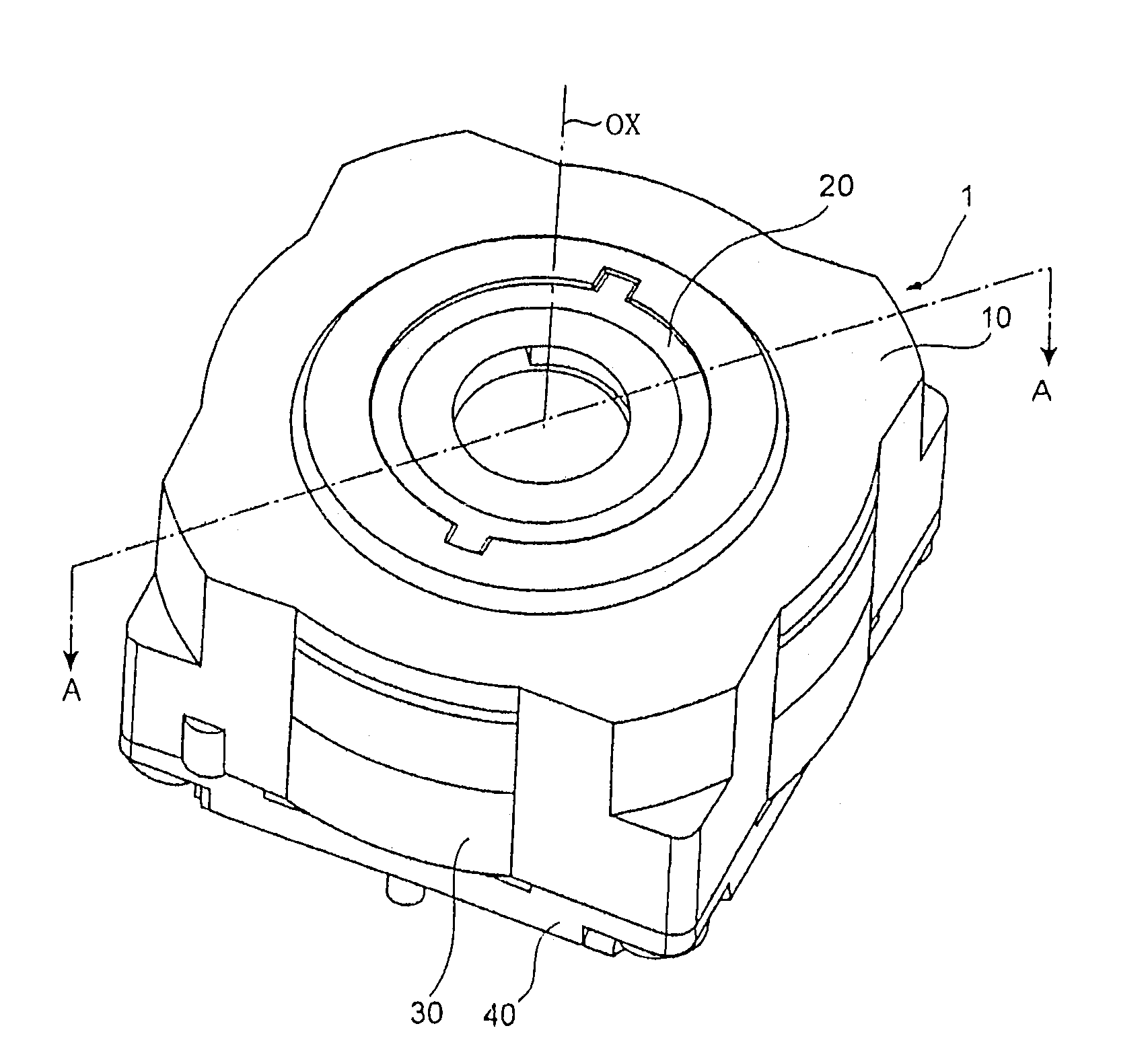
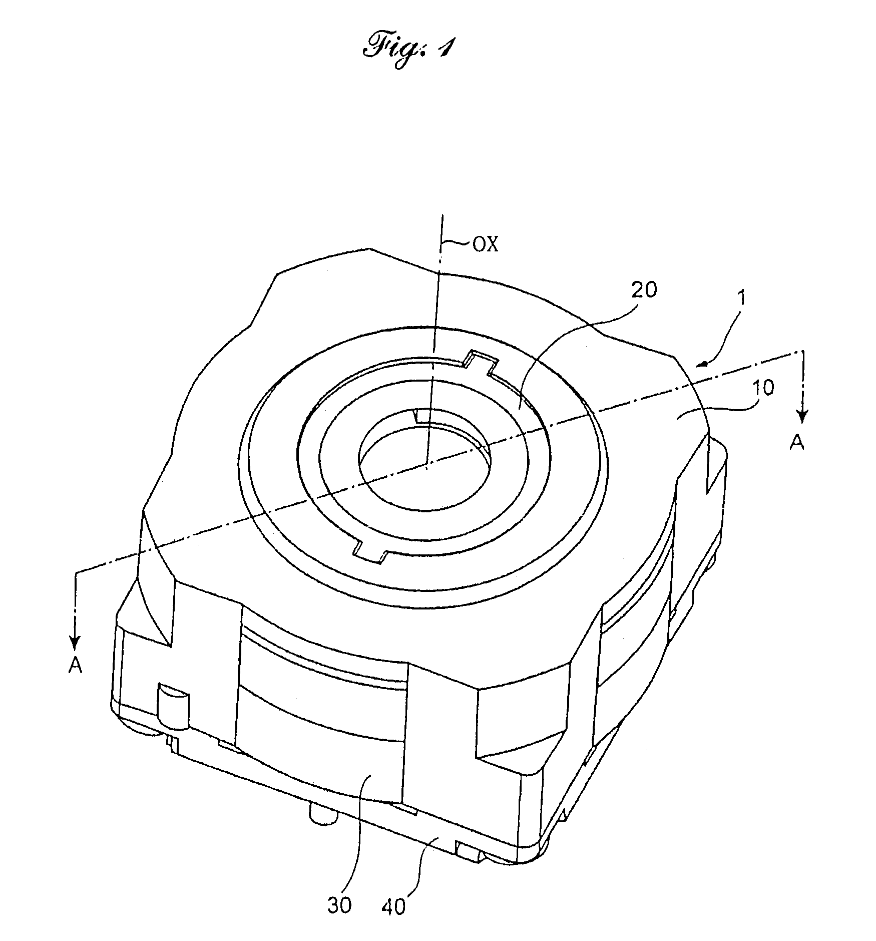
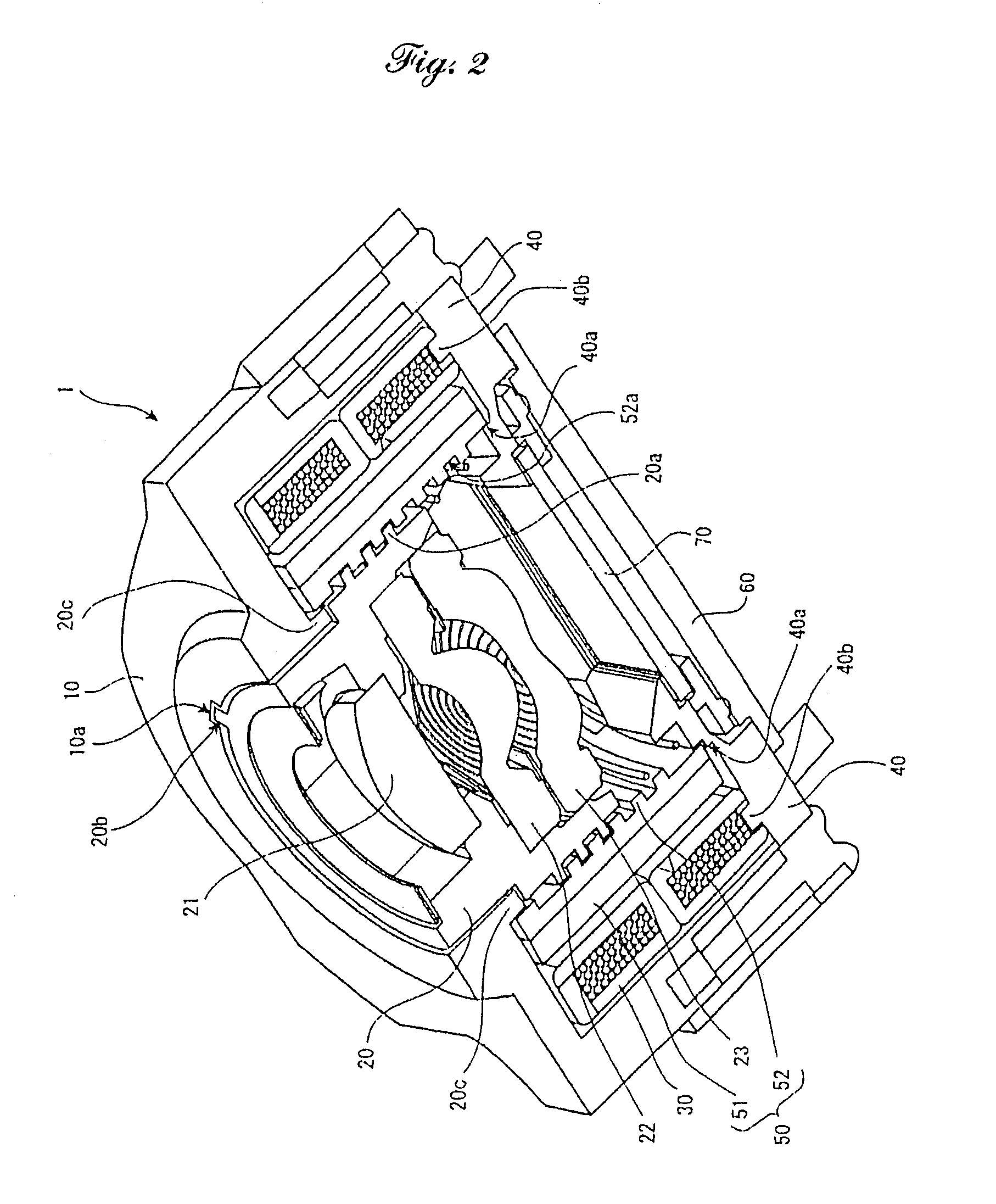
[0020]Referring to the accompanying drawings in detail, and in particular, to FIGS. 1 and 2 showing an image pickup device 1 that is installed in, for example, a mobile phone, the image pickup device 1 has an automatic focusing feature. Automatic focusing is performed by moving one or more lenses in a direction along an optical axis (which is hereafter referred to as an axial direction) OX. The image pickup unit 1 includes a stepping motor and an optical lens system both of which are disposed within a unit casing comprising a housing shell made up of two mating shell halves, namely a front housing shell 10 having a top flange and a rear housing shell 40 having a bottom flange coupled with each other with set screws (not shown). The stepping motor comprises a cylindrical stator 30 and a cylindrical rotor 50. The optical lens system, which may be of a single component type or a multiple component type, comprises, for example in this example, three lens elements, namely first, second a...


PUM


Abstract

A drive unit for performing precise linear movement of a driven object comprises a motor having a cylindrical stator and a cylindrical rotor that is coaxially put in the cylindrical stator and capable of rotating relatively to the cylindrical stator, a movable barrel for holding a driven object mounted for rotation in the cylindrical rotor, a motion transformation mechanism comprising an internal helical groove formed in the cylindrical rotor and an external helical thread formed on the movable barrel which engage with each other so as to cause relative rotation between the cylindrical rotor and the movable barrel when the cylindrical rotor rotates, thereby transforming rotational movement of the rotor into a linear movement of the movable barrel, and a head-on striking structure provided between the helical groove and the helical thread to restrict the relative rotation at an intended extreme end of an axial path of the movable barrel.

Description

BACKGROUND OF THE INVENTION[0001]1. Field of the Invention[0002]The present invention relates to a drive unit for driving a movable element and an image data pickup device equipped with the drive unit[0003]2. Description of Related Art[0004]An image pickup device for taking a picture and acquiring a digital image of the picture is incorporated in a wide range of small instruments such as mobile phones and personal digital assistance (PDA) devices. Through the instrumentality of equipping such a small insent always going with the possessor with an image pickup unit the possessor is allowed to take pictures readily without taking pains to carry on a digital camera or a video camera. The small instrument is equipped with a radio or infrared data communication function in general way and capable of being and is in an advantageous position for transmitting a picture image to other mobile phones or personal computers immediately on the scene, in consequence.[0005]The image pickup device i...

Claims


Application Information

Patent Timeline
Patent Type & Authority Patents(United States)
IPC IPC(8): H02K41/00G02B7/02
CPCH02K7/06H02K37/14
Inventor MANABE, MITSUO
Owner FUJI PHOTO OPTICAL CO LTD
Why Eureka
Try Eureka