Power strip with control and monitoring functionality

a technology of power strips and functionality, applied in the field of home appliance control, can solve the problems of high programming skill, high cost of systems, and widespread adoption of consumer us

Inactive Publication Date: 2007-09-25
UNIVERSAL ELECTRONICS INC
View PDF10 Cites 148 Cited by
  • Summary
  • Abstract
  • Description
  • Claims
  • Application Information

AI Technical Summary

Benefits of technology

[0009]Also disclosed is a power strip having power monitoring functionality as well as controlling functionality. More particularly, the power strip, i.e., a plurality of ganged outlets adapted to receive appliance plugs, may operate to support power status reporting as well as the issuing of commands to control functional operations of the appliances. For example, the power strip may receive a command from a remote control (for example transmitted via radio frequency or wired connection) and, in turn, issue a corresponding command (for example transmitted via infrared) to one or more appliances to cause the one or more appliances to perform a functional operation. As will be appreciated, this ability for the power strip to command functional operations of the appliances will have the advantage of allowing appliances that are responsive to infrared commands to be placed in a location, such as behind the closed doors of a cabinet, etc., that would not normally allow such appliances to be easily controlled by a user.

Problems solved by technology

While these known systems work for their intended purpose, they have not been widely adopted for use by consumers for the reason that they suffer numerous drawbacks.
In this regard, the systems are expensive to purchase and installation (e.g., wiring of the components) often requires the assistance of a professional.
Programming the central controller also requires a high-level of programming skill that most consumers find intimidating or are simply unable to comprehend.
While remote controls having macro command capabilities have been widely accepted and used by consumers, there is a particular problem associated with the use of macros.
When a macro is programmed to transmit power control commands to an appliance (e.g., a macro programmed to turn on a VCR, turn on a television, and tune the television to channel 3), there is no easy way to ensure that the appliance is in a known state when the macro is executed.
Thus, there is no easy way to ensure that the desired operations will be performed when the macro is executed.
In the example provided, if the television were already powered on prior to executing the macro, executing the macro might send a power toggle command to the television that would not have the desired effect of turning the television on.
Rather, to the frustration of a user, the power toggle command in the executing macro would cause the already powered on television to turn off and the tune to channel 3 command would not be capable of being operated upon by the now powered off television.
This, however, defeats the purpose of providing a remote control with macro command capabilities as the user must then control power to an appliance by conventionally activating keys on the remote control or by manually turning on / off the appliances.
This solution is also not acceptable as it requires the user to have a knowledge of the intricacies of the operation of an appliance which is knowledge that most consumers fail to possess.
Furthermore, even if the consumer had such knowledge of appliance operation, this solution requires that the appliance be placed in a state that might not be desired by the consumer thereby creating a further problem that needs to be addressed (e.g., by requiring the consumer to add further steps to a programmed macro).

Method used


Image

  • Power strip with control and monitoring functionality
  • Power strip with control and monitoring functionality
  • Power strip with control and monitoring functionality

Examples


Embodiment Construction

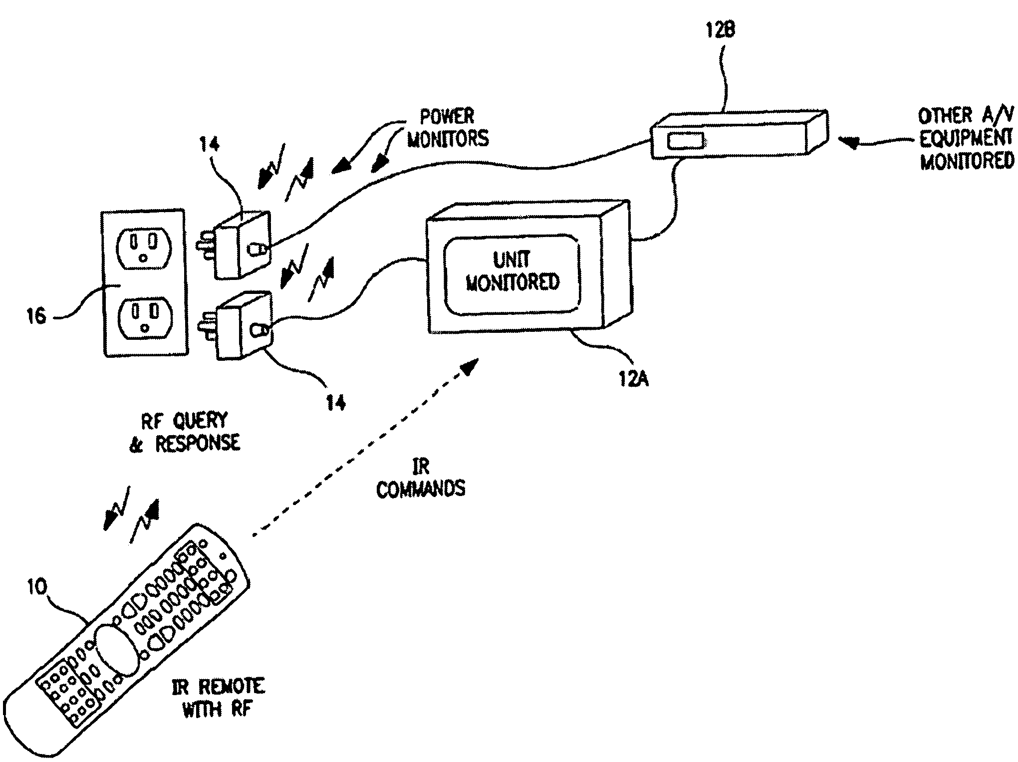
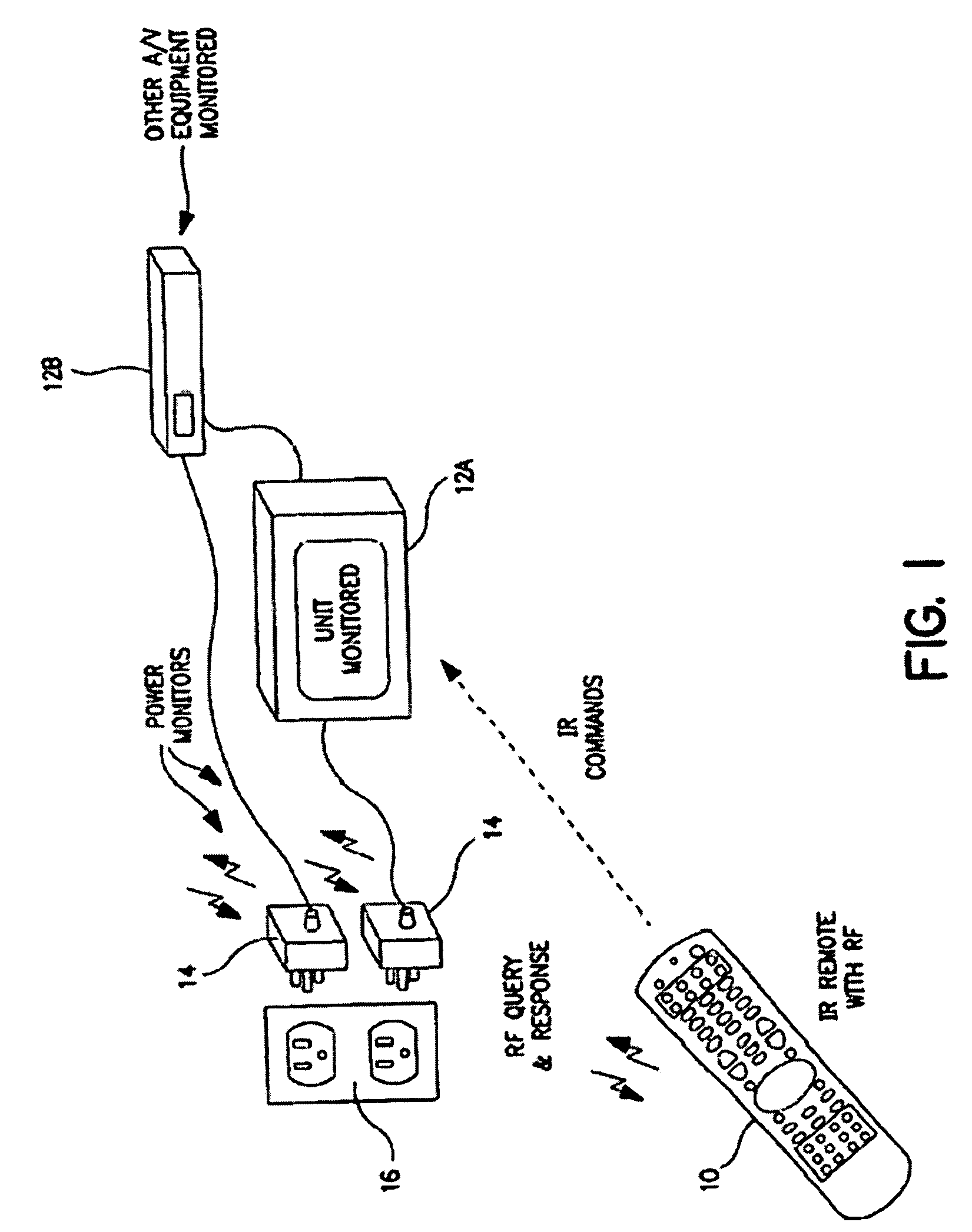
[0031]Turning now to the figures, wherein like reference numerals refer to like elements, there is illustrated in FIG. 1 a system for providing a remote control with appliance power awareness. Generally, the system includes a remote control 10 capable of commanding the operation of home appliances 12, such as television 12a and set-top box 12b. It will be appreciated that the home appliances 12 can be of different types (such as, by way of example only, televisions, VCRs, DVD players, set-top boxes, amplifiers, CD players, game consoles, home lighting, drapery, etc.) manufactured by different manufacturers. The home appliances 12 receive power from an electrical outlet 16 using an intermediate power monitor unit 14 having a socket for receiving the plug of an appliance 12 and a plug for insertion into a socket of the electrical outlet 16. As will be described in greater detail, the power monitor unit 14 bi-directionally communicates with the remote control 10 to provide the remote c...


PUM


Abstract

A power strip adapted to support power status reporting as well as the issuing of commands to control functional operations of the appliances. The power strip may receive a command from a remote control (for example transmitted via radio frequency or wired connection) and, in turn, issue a corresponding command (for example transmitted via infrared) to one or more appliances to cause the one or more appliances to perform a functional operation.

Description

RELATED APPLICATION[0001]This application claims the benefit of and is a continuation-in-part of U.S. application Ser. No. 10 / 654,180, filed Sep. 3, 2003, now U.S. Pat. No. 6,870,463, and U.S. application Ser. No. 10 / 758,820, filed Jan. 16, 2004, both of which claim the benefit of U.S. application Ser. No. 10 / 087,078, filed Mar. 1, 2002 (now U.S. Pat. No. 6,642,852).BACKGROUND OF THE INVENTION[0002]The present invention relates generally to home appliance control and, more particularly, to a power strip having control and monitoring functionality, especially for use in conjunction with a remote control device with appliance power awareness.[0003]In the art it is known to monitor power supplied to home appliances. For example, Niles currently markets a power sensor under the “APC-2” brand name. Similarly, Panja markets a power sensor under the “AMX”“PCS” and “PCS2” brand names. These power sensors are particularly used to monitor the state of a home appliance, i.e., whether the home ...

Claims


Application Information

Patent Timeline
Patent Type & Authority Patents(United States)
IPC IPC(8): G08C19/00H04B10/00G08C17/00G08C19/28H04N5/63
CPCG05B15/02G08C17/02G08C19/28G08C23/04H04N5/4403H04N21/4131H04N21/42221G08C17/00H04N21/43615G08C2201/33G08C2201/40G08C2201/50H04N5/63H04N2005/4425H04N21/4221H04N21/4222H04N21/42204
Inventor DRESTI, MAUROKLEIN, SANDRO D.HAYES, PATRICK H.
Owner UNIVERSAL ELECTRONICS INC
Why Eureka
Try Eureka