
CCD having improved flushing by reducing power consumption and creating a uniform dark field while maintaining low dark current

Active Publication Date: 2007-09-25
SEMICON COMPONENTS IND LLC
View PDF6 Cites 7 Cited by
  • Summary
  • Abstract
  • Description
  • Claims
  • Application Information

AI Technical Summary

Benefits of technology

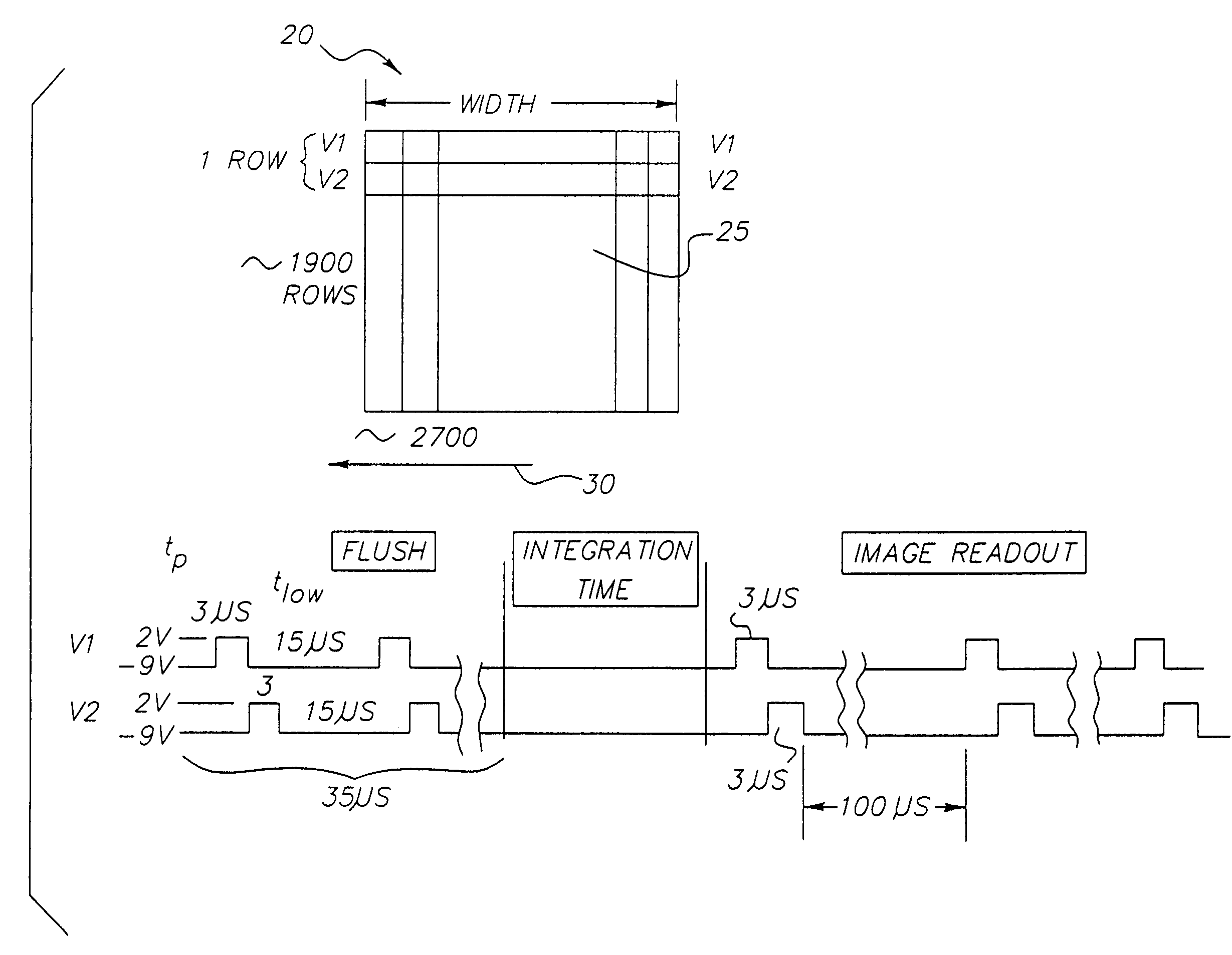
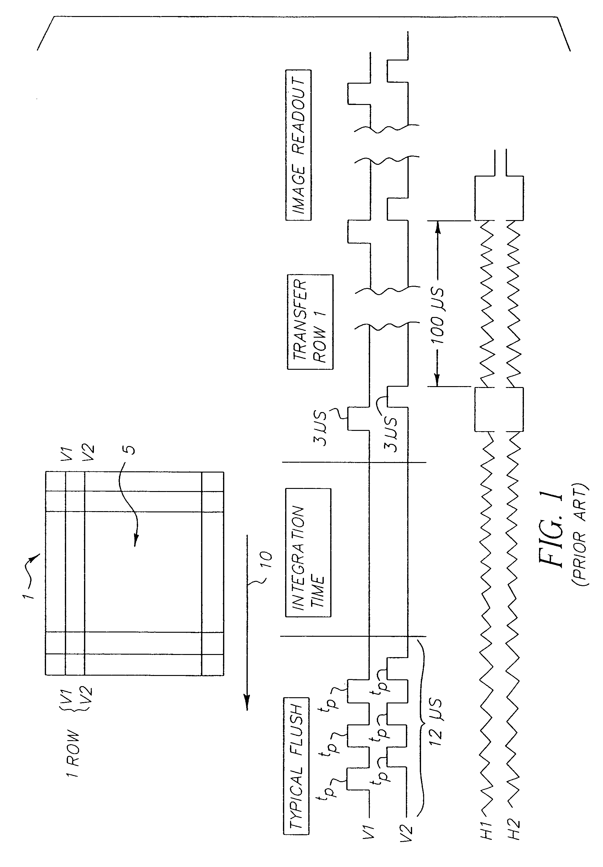
[0009]The present invention is directed to overcoming one or more of the problems set forth above. Briefly summarized, according to one aspect of the present invention, the invention includes a digital camera having (a) a CCD operating with accumulation mode clocking for capturing an electronic representation of an image; and (b) two or more clocks operatively respectively connected to each phase of the two or more phases for initiating flushing of excess current, wherein, to initiate flushing, a time the clocks are at a high level are substantially the same, and a time tlow the clocks are at a low level can be shortened from its normal operating duration during image readout to a minimum width, tmin, at which their dark current starts to substantially increase for reducing power consumption while retaining minimum dark current and for having a substantially uniform dark field. The time tlow for the present invention is greater than tlow=tp for the prior art. The time tlow can be increased from tmin to approximately twice the normal line readout time, tline, in order to compromise between increased flush time and reduced power consumption without noticeably affecting dark current.
[0011]The present invention has the following advantages of reducing the power consumption and creating a uniform dark field while maintaining low dark current although flush time will be slightly longer than in the prior art.

Problems solved by technology

Although the presently known CCDs are satisfactory, they include drawbacks.
Such prior art devices have high power consumption during flush and non-uniform dark fields.
Such non-uniform dark fields will create a non-uniform background for which correction is required and shot noise from the higher dark current will add to the image noise.

Method used


Image

  • CCD having improved flushing by reducing power consumption and creating a uniform dark field while maintaining low dark current
  • CCD having improved flushing by reducing power consumption and creating a uniform dark field while maintaining low dark current
  • CCD having improved flushing by reducing power consumption and creating a uniform dark field while maintaining low dark current

Examples


Embodiment Construction

[0017]Referring to FIG. 3, there is shown a two-phase CCD 20 having a plurality of pixels 25 of the present invention with its clocking scheme. The pixels 25 are arranged in an array of rows and columns, 1900×2700 in the preferred embodiment for illustrating an exemplary embodiment, although other configurations are obviously also suitable. It is instructive to note that, although a two-phase device is shown, there may be more than two phases as long as the device can be operated in accumulation mode clocking. Accumulation mode is disclosed in U.S. Pat. No. 5,115,458, by Burkey et al., titled “Reducing Dark Current In Charge Coupled Devices,” and in “Solid State Imaging with Charge-Coupled Devices,” by Albert J. P. Theuwissen and will not be discussed herein.

[0018]In regard to the operation of the present invention during flushing, the vertical clocking includes clocking V1 high for a predetermined time, preferably the minimum time necessary for good vertical transfer efficiency, an...


PUM


Abstract

A digital camera includes a CCD operating with accumulation mode clocking for capturing an electronic representation of an image; and two or more clocks operatively and respectively connected to each phase of the two or more phases for initiating flushing of excess current, wherein, to initiate flushing, a time the clocks are at a high level are substantially the same, and a time the clocks are at a low level can be selected at any duration between a minimum width at which dark current starts to substantially increase and twice its normal operating duration during image readout and for reducing power consumption while retaining minimum dark current and for having a substantially uniform dark field.

Description

CROSS-REFERENCE TO RELATED APPLICATIONS[0001]Reference is made to and priority claimed from U.S. Provisional Application Ser. No. 60 / 347,524, filed Jan. 11, 2002, entitled SLOW FLUSH CLOCKING.[0002]The present application is related to U.S. application Ser. No. 10 / 268,449, filed Oct. 10, 2002, by Gregory O. Moberg et al., and entitled, “A METHOD FOR REDUCING SHUTTER LATENCY WHILE MAINTAINING LOW DARK CURRENT IN AN IMAGER AND MINIMIZING ENERGY CONSUMPTION, ” in which reference is made to and priority claimed from U.S. Provisional Application Ser. No. 60 / 347,551, filed Jan. 11, 2002, entitled “SLOW FLUSH CLOCKING.”FIELD OF THE INVENTION[0003]The invention relates generally to the field of image sensors and, more particularly, to such image sensors having improved flushing of excess charge by reducing the power consumption and creating a uniform dark field while maintaining low dark current.BACKGROUND OF THE INVENTION[0004]Typically, a true two phase CCD (charge-coupled device) refers ...

Claims


Application Information

Patent Timeline
IPC IPC(8): H04N9/64H04N3/14H04N5/335H01L27/148H04N3/15H04N5/361H04N5/378
CPCH04N3/1568H04N5/23241H04N5/335H04N5/361H04N5/378H04N25/63H04N25/709H04N25/75H04N25/00
Inventor SHEPHERD, JOHN P.MEISENZAHL, ERIC J.BROLLY, RICHARD
Owner SEMICON COMPONENTS IND LLC
Learn More