
Optical detection apparatus for multi-channel multi-color measurement and multi-channel sample analyzer employing the same

a detection apparatus and multi-color technology, applied in the direction of optical radiation measurement, instruments, spectrometry/spectrophotometry/monochromators, etc., can solve the problems of increasing the production cost of multi-channel sample analyzers, too many optical detectors and filters, and high accuracy required for fluorescent analysis. , to achieve the effect of low production cost and small siz

Active Publication Date: 2007-09-25
SAMSUNG ELECTRONICS CO LTD
View PDF14 Cites 91 Cited by
  • Summary
  • Abstract
  • Description
  • Claims
  • Application Information

AI Technical Summary

Benefits of technology

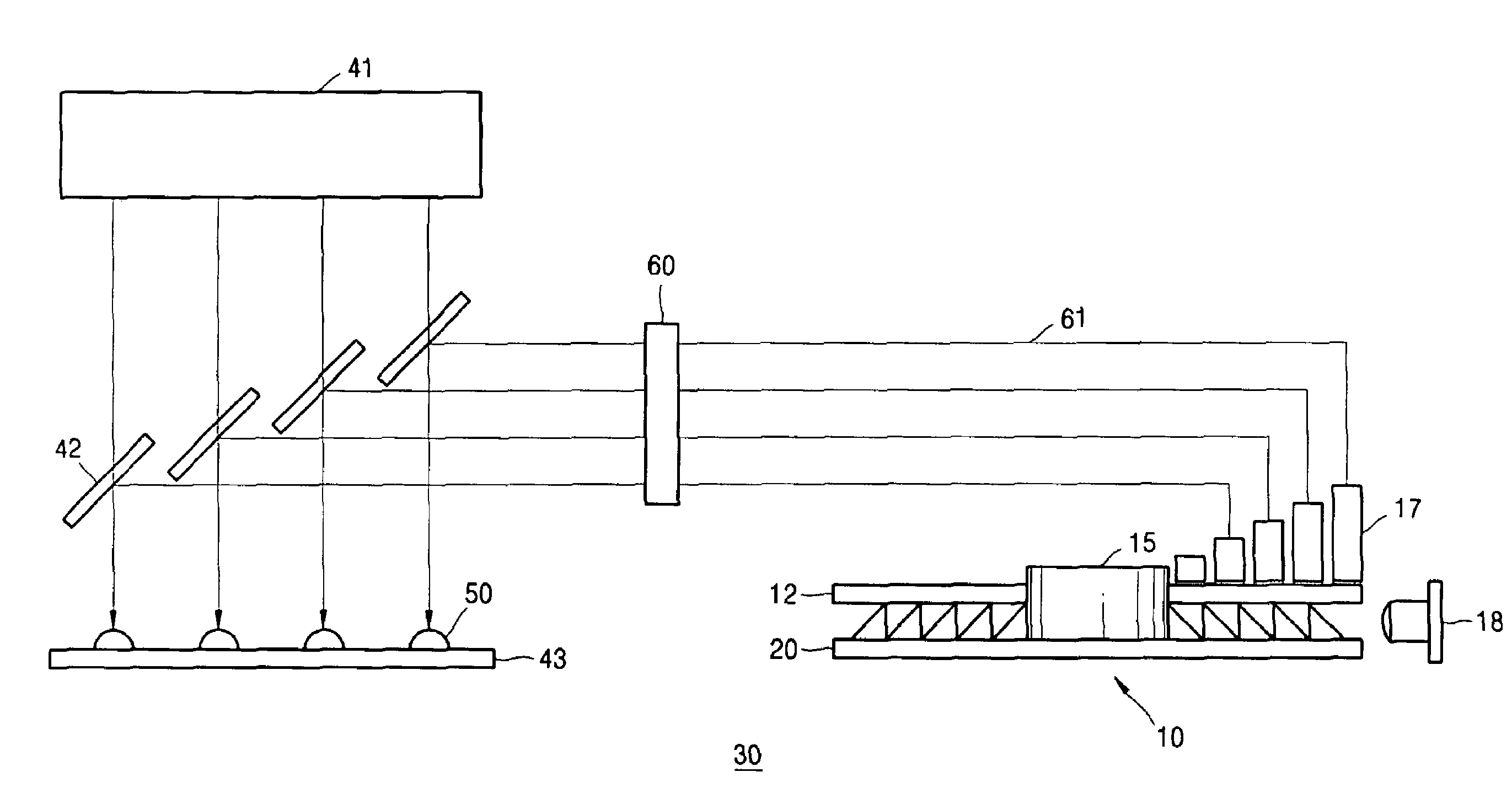
The present invention provides an optical detection apparatus that can measure multi-channel samples at high speed and various wavelengths using an optical detector and a multi-channel sample analyzer employing the same. The apparatus has a small size and low production costs and can be used for multi-channel multi-color measurement. The apparatus includes an optical detector, a filter wheel with at least two color filters connected to each other, a plurality of optical channels through which a plurality of beams of light enter the filter wheel, and a mirror unit including a plurality of mirrors for sequentially reflecting the plurality of beams of light transmitted through the filter wheel to the optical detector, wherein the mirrors are disposed at different azimuthal angles from one another on the mirror unit such that the beams of light exiting the optical channels are sequentially reflected to the optical detector during the rotation of the mirror unit. The apparatus can measure various samples simultaneously and can be used in various fields such as biological research and medical diagnosis.

Problems solved by technology

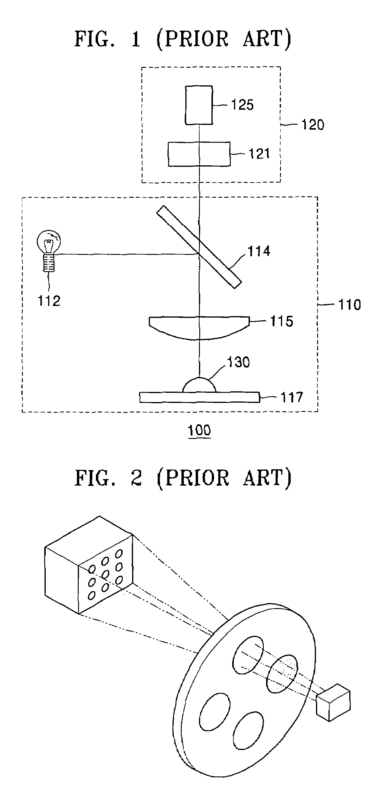
Thus, too many optical detectors and filters are used relative to the number of samples.
However, a CCD having a large area and a high accuracy required for fluorescent analysis is very expensive, thus increasing the production costs of the multi-channel sample analyzer and being unsuitable for small analyzers.
However, since a frame rate (the number of images which a CCD reads per second), which is related to a resolution of the CCD measurement, is limited, an increase in speed of the filter wheel is limited.
Thus, there is still a limit when measuring many wavelengths at high speed.

Method used


Image

  • Optical detection apparatus for multi-channel multi-color measurement and multi-channel sample analyzer employing the same
  • Optical detection apparatus for multi-channel multi-color measurement and multi-channel sample analyzer employing the same
  • Optical detection apparatus for multi-channel multi-color measurement and multi-channel sample analyzer employing the same

Examples


Embodiment Construction

[0027]Hereinafter, the constitution and operation of an optical detection apparatus for multi-channel multi-color measurement according to an embodiment of the present invention and a multi-channel sample analyzer employing the same will be described in more detail with reference to the attached drawings.

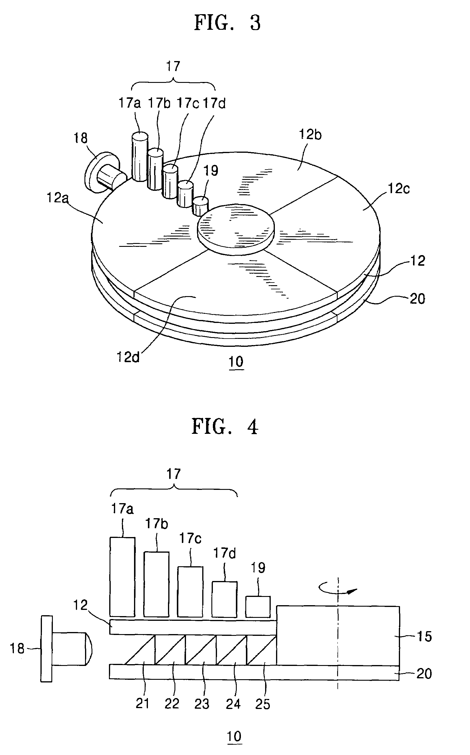
[0028]FIG. 3 is a schematic perspective view of an optical detection apparatus 10 according to an embodiment of the present invention. Referring to FIG. 3, the optical detection apparatus 10 comprises an optical detector 18, for example, a photo multiplier tube (PMT), a filter wheel 12 having first through fourth color filters 12a through 12d connected to each other to form a disk form, a plurality of optical channels 17 and 19 through which a plurality of wavelengths of light enter the filter wheel 12, and a mirror unit 20 having a plurality of mirrors 21 through 25 that sequentially reflect the wavelengths of light transmitted through the filter wheel 12 to the optical detector 18...


PUM

PropertyMeasurementUnit
radiusaaaaaaaaaa
radiusaaaaaaaaaa
opticalaaaaaaaaaa

Abstract

Provided are an optical detection apparatus which can measure multi-channel samples at high speed and various wavelengths using an optical detector and a multi-channel sample analyzer employing the same. The optical detection apparatus includes an optical detector; a filter wheel having at least two color filters connected to each other in the shape of a disk; a plurality of optical channels through which a plurality of beams of light enter the filter wheel; and a mirror unit including a plurality of mirrors for sequentially reflecting the plurality of beams of light transmitted through the filter wheel to the optical detector, wherein the mirror unit rotates together with the filter wheel.

Description

BACKGROUND OF THE INVENTION[0001]This application claims the benefit of Korean Patent Application No. 10-2004-0071224, filed on Sep. 7, 2004, in the Korean Intellectual Property Office, the disclosure of which is incorporated herein in its entirety by reference.[0002]1. Field of the Invention[0003]The present invention relates to an optical detection apparatus for multi-channel multi-color measurement and a multi-channel sample analyzer employing the same, and more particularly, to an optical detection apparatus which can measure multi-channel samples at high speed and various wavelengths using an optical detector and a multi-channel sample analyzer employing the same.[0004]2. Description of the Related Art[0005]A method of analyzing components of a sample which includes irradiating a specific wavelength of light onto the sample and then detecting a spectrum of light which is emitted from the sample is well known. For example, the respective bases of DNA can be labeled with fluoresc...

Claims


Application Information

Patent Timeline
Patent Type & Authority Patents(United States)
IPC IPC(8): G01N21/25G01J3/51
CPCG01J3/51G01N21/645G01N2021/6421G01N2021/6471G01N21/276G01N2223/412
Inventor OK, GYEONG-SIKKIM, JIN-TAEOH, KWANG-WOOKKIM, SANG-HYO
Owner SAMSUNG ELECTRONICS CO LTD
Learn More