Rotating carriage assembly for use in scanning cargo conveyances transported by a crane

a technology of rotating carriages and cargo conveyances, which is applied in the direction of passenger handling apparatuses, special-purpose vessels, instruments, etc., can solve the problems of system components twisting, interfering with or preventing accurate scanning, etc., and achieve the effect of reducing or eliminating unwanted twisting of the carriag

Inactive Publication Date: 2007-09-25
VAREX IMAGING CORP
View PDF61 Cites 53 Cited by
  • Summary
  • Abstract
  • Description
  • Claims
  • Application Information

AI Technical Summary

Benefits of technology

[0014]More specifically, an embodiment of a radiation scanning technique is provided for scanning an object, wherein a crane system moves the object from a first location to a second location. A radiation source and a radiation detector are proximate to the crane system and positioned such that the object may be moved between the source and the detector by the crane system. A carriage is coupled to the crane system to engage the object and to move the object from the first location to the second location. The carriage may be coupled to the object. The carriage is configured to rotate the object for scanning. A rotatable member may be coupled to the carriage. The rotatable member is rotatable in a second direction opposite to the first direction, to counterbalance angular momentum generated by the rotating cargo conveyance. This decreases or eliminates unwanted twisting of the carriage and cargo conveyance during rotation.

Problems solved by technology

Rotation of an object as large as a shipping container suspended by a crane could generate a large amount of angular momentum that could cause twisting of system components, interfering with or preventing accurate scanning.

Method used


Image

  • Rotating carriage assembly for use in scanning cargo conveyances transported by a crane
  • Rotating carriage assembly for use in scanning cargo conveyances transported by a crane
  • Rotating carriage assembly for use in scanning cargo conveyances transported by a crane

Examples


Embodiment Construction

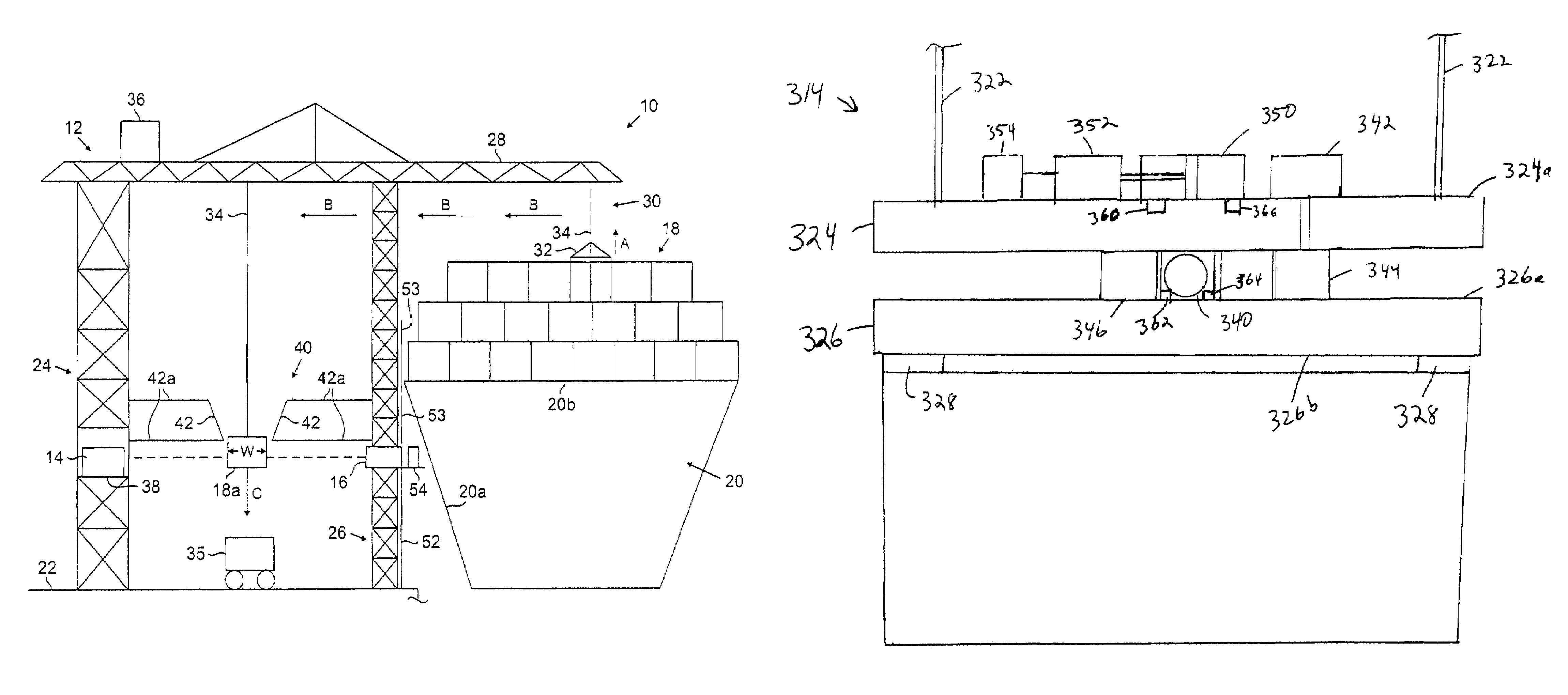
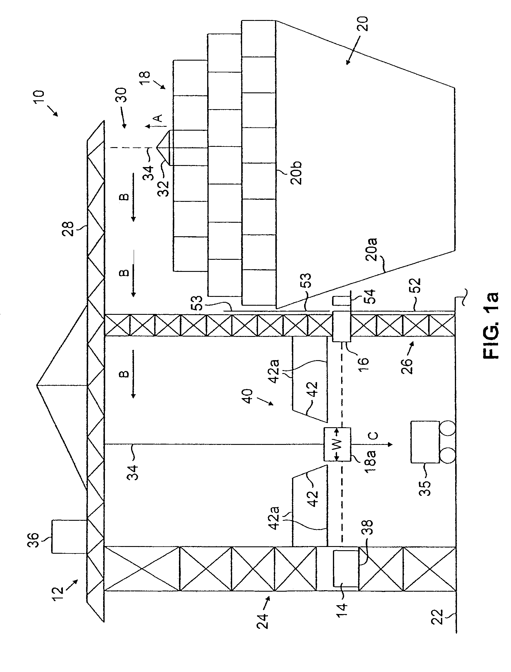
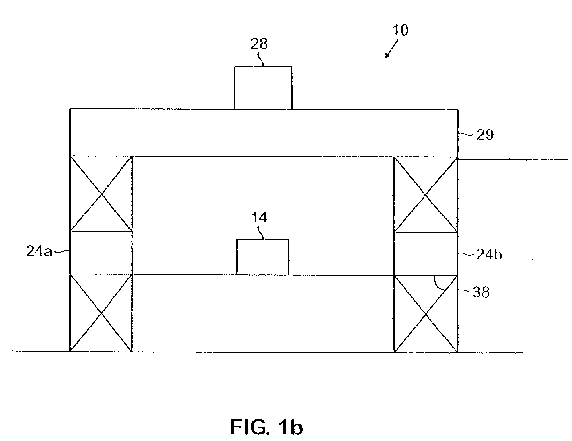
[0038]FIGS. 1a-10 show embodiments of radiation scanning systems for use at seaports, for example, disclosed in application Ser. No. 10 / 356,101, which was filed on Jan. 31, 2003, is assigned to the assignee of the present invention, and is incorporated by reference herein. FIG. 1a is a schematic representation of a radiation scanning system 10 comprising a crane system 12 supporting a radiation source 14 and a radiation detector 16. The crane system 12 may be a standard crane for unloading and loading cargo conveyances 18, such as sea containers and pallets, for example, from a ship 20 at a dock or seaport 22, as is known in the art. In this example, the crane system 12 may be any device used to lift an object from one location and lower the object onto another location.

[0039]The crane system 12 comprises opposing vertical structures 24, 26 supporting a boom arm 28. A conveying system 30 is supported by the boom arm 28. The conveying system 30, the details of which are not shown but...


PUM

PropertyMeasurementUnit
widthaaaaaaaaaa
energyaaaaaaaaaa
energyaaaaaaaaaa

Abstract

In one example, a radiation scanning system and method rotates a cargo conveyance after removal from a ship for proper orientation with respect to a scanning source and detector, for scanning. A movable carriage may be provided on a crane system, to rotate the cargo conveyance. A rotating flywheel on the carriage rotates in a direction opposite the direction of rotation of the cargo conveyance, to counterbalance angular momentum generated by the rotating conveyance, to avoid or minimize twisting of the carriage. Feedback is provided to control the rotation of the flywheel. Once the cargo conveyance is in the predetermined position, the conveyance is moved between the radiation source and detector for scanning by a vertically extending radiation beam.

Description

[0001]The present application is a continuation-in-part of application Ser. No. 10 / 356,101, which was filed on Jan. 31, 2003, is assigned to the assignee of the present invention, and is incorporated by reference herein.FIELD OF INVENTION [0002]The invention relates to methods and systems for radiation scanning of objects, and more particularly, to a system and method for rotating and radiation scanning of cargo conveyances for the detection of contraband.BACKGROUND OF INVENTION [0003]Radiation is commonly used in the non-invasive inspection of objects such as luggage, bags, briefcases, and the like to identify hidden contraband. Contraband includes guns, knives, explosive devices, as well as illegal drugs, for example. As criminals and terrorists have become more creative in the way they conceal contraband, the need for more effective non-invasive inspection techniques has grown. While the smuggling of contraband onto planes in carry-on bags and in luggage has been a well-known, on...

Claims


Application Information

Patent Timeline
Patent Type & Authority Patents(United States)
IPC IPC(8): G01N23/04B63B27/10G21K5/10
CPCG01N23/04G21K5/10G01V5/005B66C13/16B66C19/002G01V5/0008
Inventor CLAYTON, JAMES E.BJORKHOLM, PAUL
Owner VAREX IMAGING CORP
Why Eureka
Try Eureka