Spin transfer MRAM device with novel magnetic synthetic free layer

a magnetic transfer and synthetic free technology, applied in the field of spin transfer mram devices with novel magnetic synthetic free layers, can solve the problems of increasing power consumption, affecting the use of magnetic fields externally generated by current carrying lines to switch the magnetic moment directions, etc., and achieves the effect of minimizing the magnitude of current and zero net magnetic momen

Active Publication Date: 2008-10-02
TAIWAN SEMICON MFG CO LTD
View PDF11 Cites 42 Cited by
  • Summary
  • Abstract
  • Description
  • Claims
  • Application Information

AI Technical Summary

Benefits of technology

[0017]A first object of this invention is to provide a CPP-MTJ configured MRAM device of the spin transform variety in which the ratio DR / R is significantly enhanced.
[0018]A second object of the present invention is to provide such a device in which the spin angular momentum deposition rate is increased.
[0019]A third object of the present invention is to provide a CPP-MTJ configured MRAM device in which the critical spin transfer current density is reduced.
[0021]These objects will be met by a device design in which MgO serves as a tunneling barrier layer in the MTJ portion of the device, Cr (or Cu) serves as the spacer layer in the spin-valve GMR portion of the device and the free layer is a synthetic exchange coupled lamination. This lamination includes two ferromagnetic layers exchange coupled across a non-magnetic layer in an antiparallel configuration of their magnetic moments (forming a synthetic anti-ferromagnetic structure) and thereby having a substantially zero net magnetic moment. This synthetic structure is then separated by a thin layer of Ta, Zr or Hf from a single ferromagnetic layer of CoFeB whose magnetization is parallel to the magnetization of its immediately adjacent ferromagnetic layer in the synthetic anti-ferromagnetic structure, thereby strongly exchange coupling to that layer (forming a synthetic ferromagnetic structure). This arrangement is seen in FIG. 4, which will be fully discussed below. This novel synthetic free layer interacts with the spin magnetic moments of a flow of conduction electrons both by transmission and reflections, thereby minimizing the magnitude of the current required to change the free layer magnetic moment.

Problems solved by technology

The use of magnetic fields externally generated by current carrying lines to switch the magnetic moment directions becomes problematic as the size of the MRAM cells decreases and, along with their decrease, so does the width of the current carrying lines.
The smaller width lines require greater currents to produce the necessary switching fields, greatly increasing power consumption.
Since a low critical spin transfer current also requires a low magnetic moment of the free layer (7), which yields a lower energy barrier to the flipping of the magnetization direction, thermal instability (fluctuations in magnetization caused by thermal energy transfers) becomes a problem when the size of the MRAM cell becomes very small and domain structures do not provide the necessary stabilization.

Method used


Image

  • Spin transfer MRAM device with novel magnetic synthetic free layer
  • Spin transfer MRAM device with novel magnetic synthetic free layer
  • Spin transfer MRAM device with novel magnetic synthetic free layer

Examples


Embodiment Construction

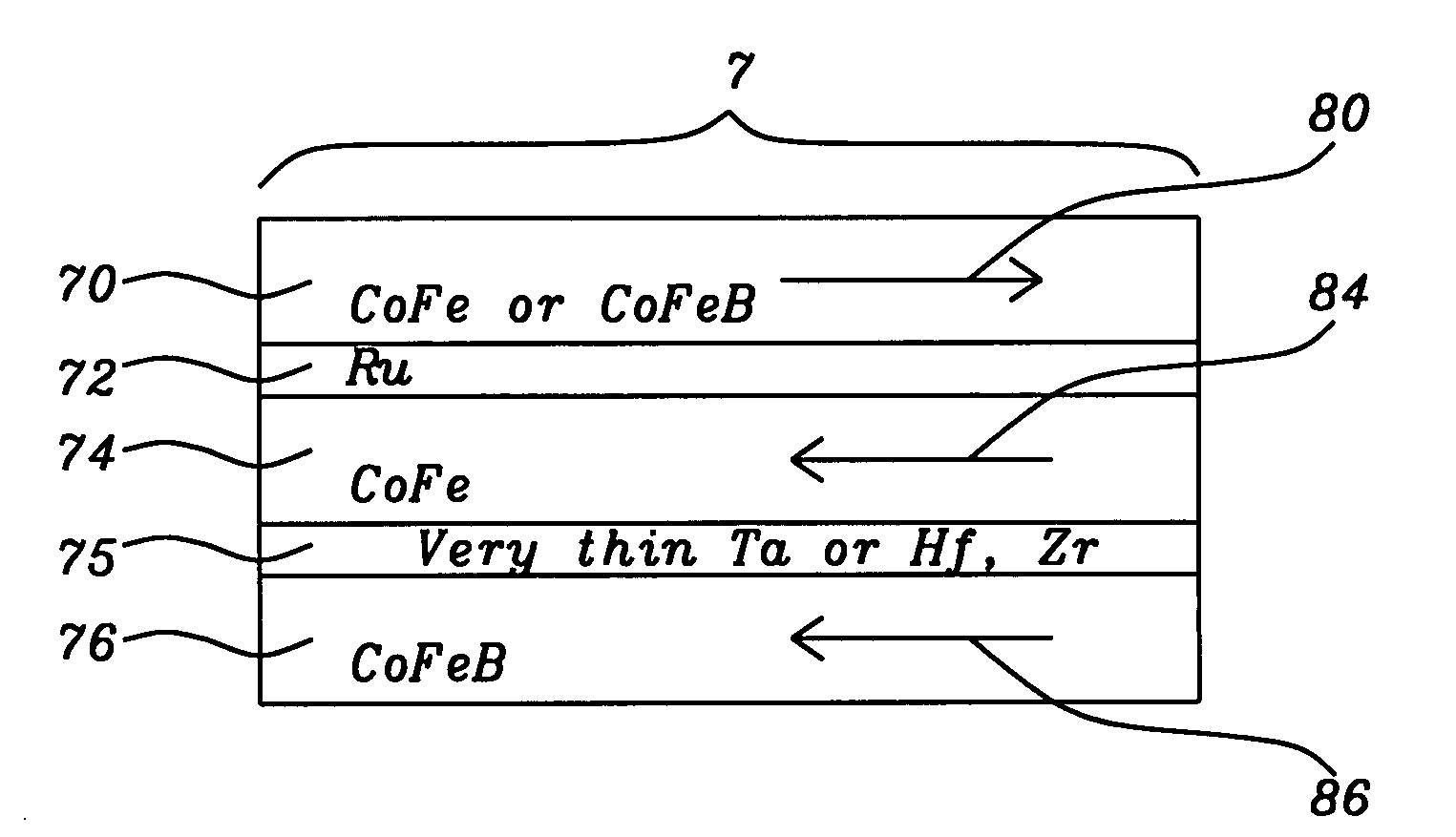
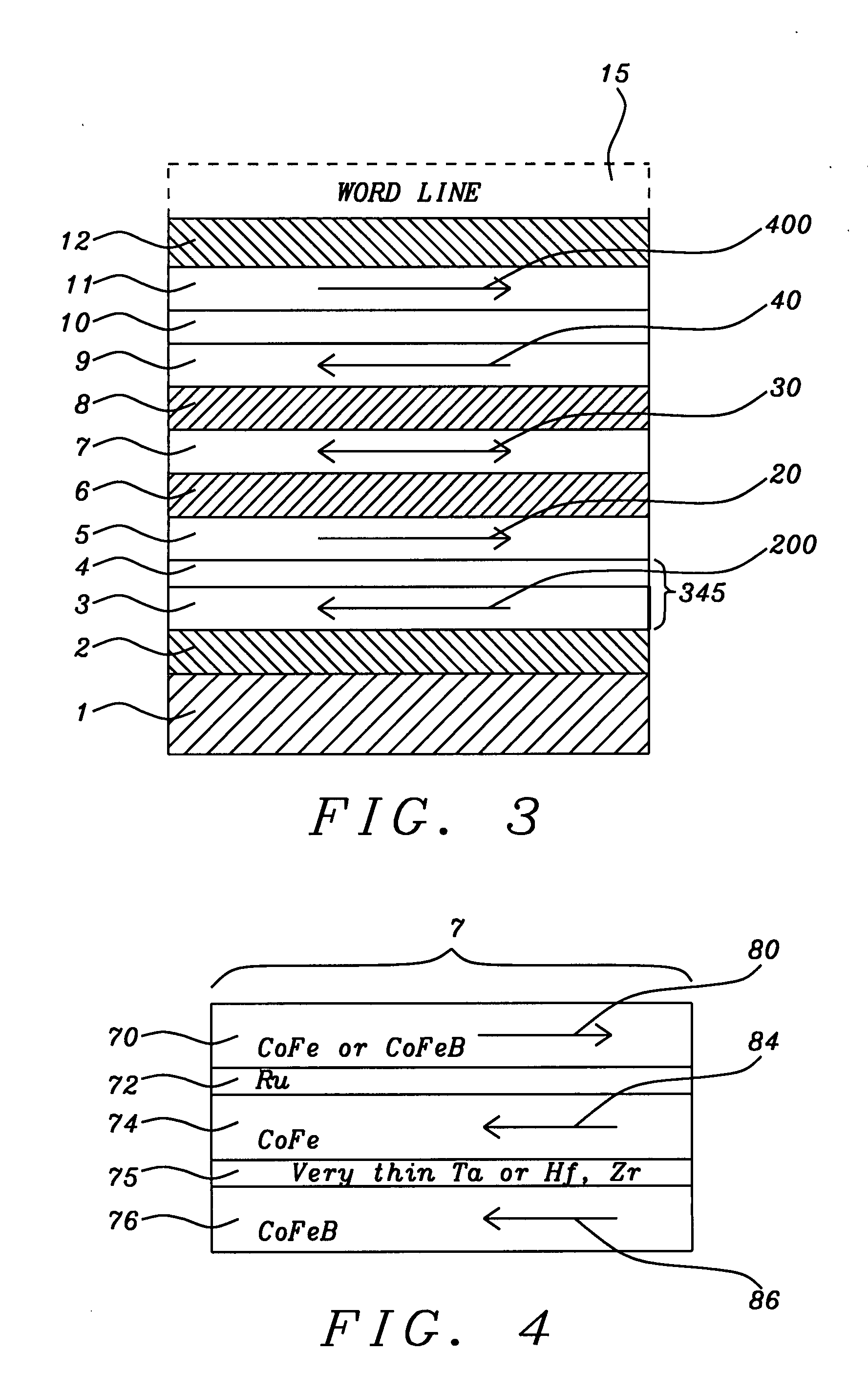
[0026]The preferred embodiment of the present invention is an MRAM device of the spin-transfer variety, having a CPP-MTJ configuration and including a free layer formed as a synthetic anti-ferromagnetically exchange coupled lamination of two ferromagnetic layers (preferably CoFe and CoFeB), then further exchange coupled by parallel magnetization coupling across a very thin layer of Ta, Zr or Hf to yet a third ferromagnetic layer of CoFeB to form a strongly exchange coupled synthetic ferromagnetic configuration. This free layer has a particularly advantageous form for a change in its magnetic moment to be effected by the transfer of spin magnetic moments of conduction electrons both by transmission and reflection.

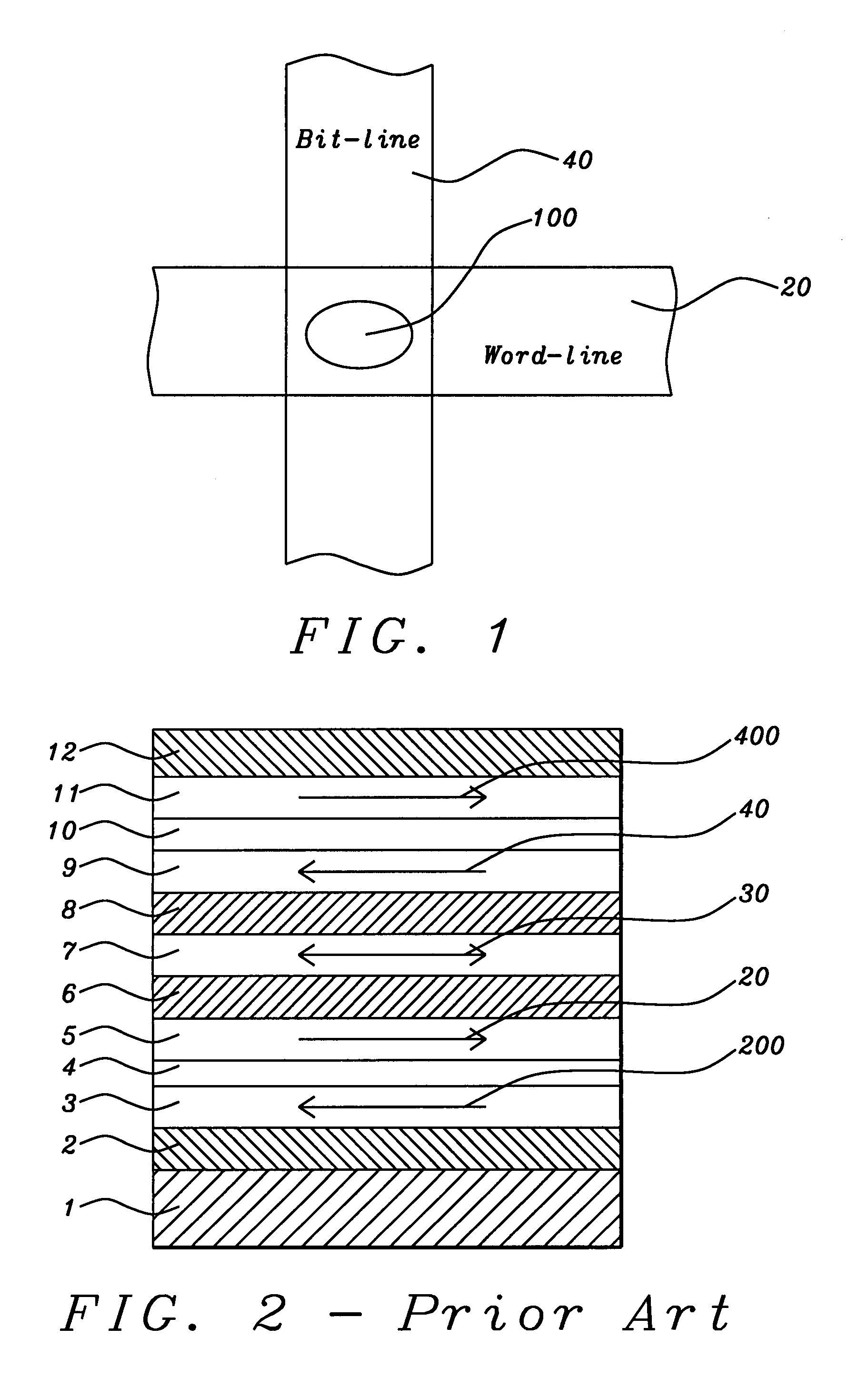
[0027]Referring to FIG. 3, there is seen a schematic cross-sectional view of the device of the present invention. Looking at the structure from the bottom upward, there is shown the following sequence of layers. Layer (1) is a substrate or underlayer. Layer (2), formed on th...


PUM

PropertyMeasurementUnit
thicknessaaaaaaaaaa
thicknessaaaaaaaaaa
thicknessaaaaaaaaaa

Abstract

We describe a CPP MTJ MRAM element that utilizes transfer of spin angular momentum as a mechanism for changing the magnetic moment direction of a free layer. The device includes a tunneling barrier layer of MgO and a non-magnetic CPP layer of Cu or Cr and utilizes a novel synthetic free layer having three ferromagnetic layers mutually exchange coupled in pairwise configurations. The free layer comprises an inner ferromagnetic and two outer ferromagnetic layers, with the inner layer being ferromagnetically exchange coupled to one outer layer and anti-ferromagnetically exchange coupled to the other outer layer. The ferromagnetic coupling is very strong across an ultra-thin layer of Ta, Hf or Zr of thickness preferably less than 0.4 nm.

Description

RELATED PATENT APPLICATION[0001]This Application is related to Docket Number HMG 06-040, filed ______ and assigned to the same assignee as the present invention.BACKGROUND OF THE INVENTION[0002]1. Field of the Invention[0003]This invention relates generally to a current perpendicular to plane random access memory (CPP-MRAM) cell formed as a magnetic tunneling junction (MTJ)) and using a spin transfer effect with enhanced spin torque.[0004]2. Description of the Related Art[0005]The conventional magnetic tunneling junction (MTJ) device is a form of ultra-high giant magnetoresistive (GMR) device in which the relative orientation of the magnetic moments of parallel, vertically separated, upper and lower magnetized layers controls the flow of spin-polarized electrons tunneling through a very thin dielectric layer (the tunneling barrier layer) formed between those layers. When injected electrons pass through the upper layer they are spin polarized by interaction with the magnetic moment o...

Claims


Application Information

Patent Timeline
Patent Type & Authority Applications(United States)
IPC IPC(8): G11B5/39
CPCB82Y25/00B82Y40/00G01R33/093H01F41/302H01F10/3254H01F10/3272G11C11/16G11C11/161
Inventor GUO, YIMINHORNG, CHENG T.TONG, RU-YING
Owner TAIWAN SEMICON MFG CO LTD
Why Eureka
Try Eureka