
Motor assembly and vacuum cleaner having the same

a technology of motor assembly and vacuum cleaner, which is applied in the direction of carpet cleaners, cleaning filter means, separation processes, etc., can solve the problems of increasing manufacturing costs, user's inability to enjoy quiet cleaning work, and complex manufacturing process of vacuum cleaner b>100/b>, so as to reduce the noise of the driving operation and the environment is quiet

Active Publication Date: 2007-10-02
SAMSUNG GWANGJU ELECTRONICS CO LTD
View PDF24 Cites 8 Cited by
  • Summary
  • Abstract
  • Description
  • Claims
  • Application Information

AI Technical Summary

Benefits of technology

"The present invention provides a motor assembly for a vacuum cleaner with an improved construction that reduces noise during operation. This is achieved by providing an auxiliary filter member that filters air a second time, and a connection path that guides air from the filter member to the vacuum cleaner's dust-collecting apparatus. The motor casing includes a first chamber and a second chamber divided therein, with a mounting member for the filter member and a cover to block the entrance opening of the cleaner body. The motor assembly also includes a suction assembly with a dirt-suctioning opening and a dust-collecting apparatus to separate dirt from external air. The invention provides a quieter environment for the user and reduces manufacturing costs."

Problems solved by technology

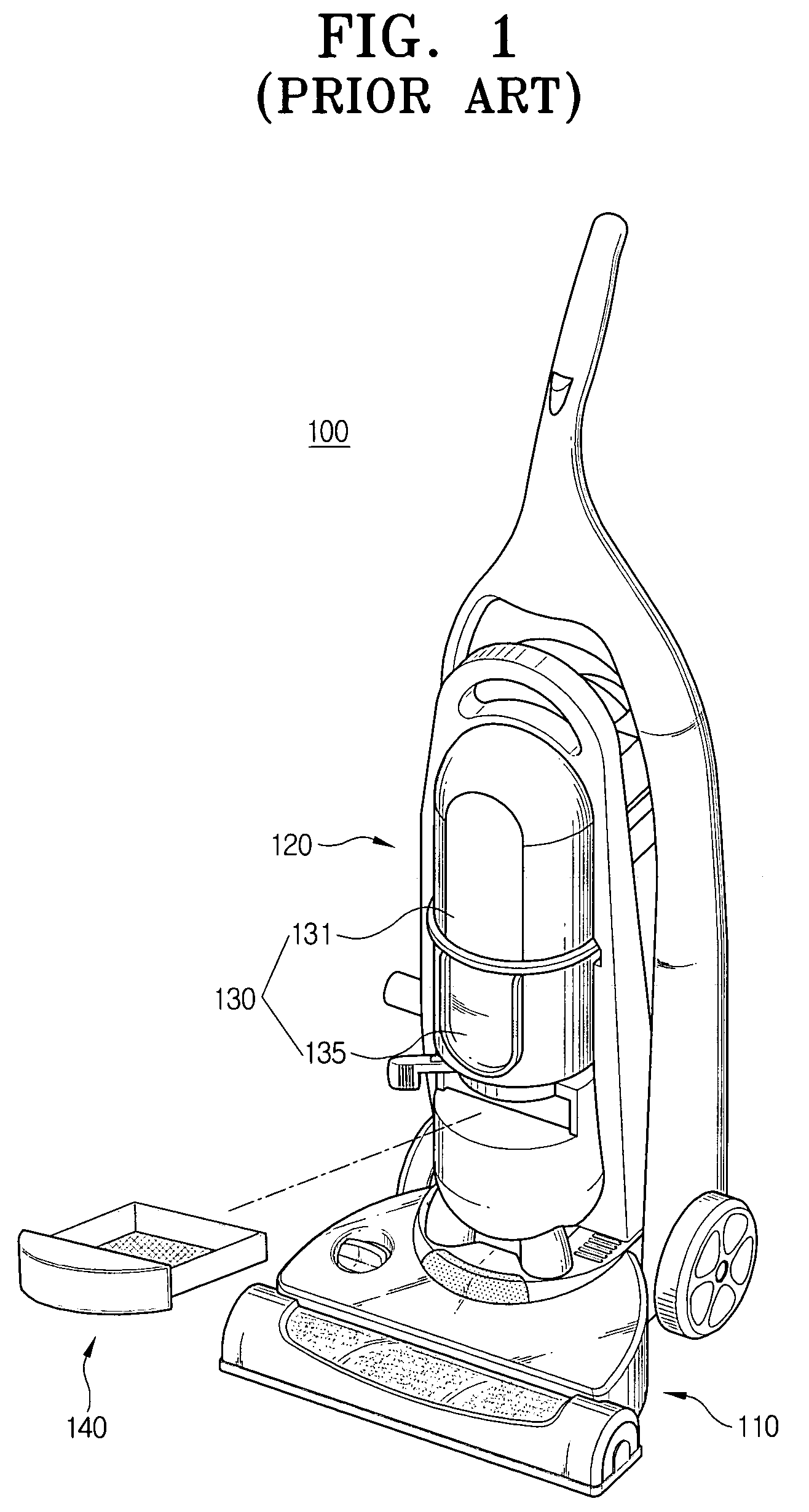
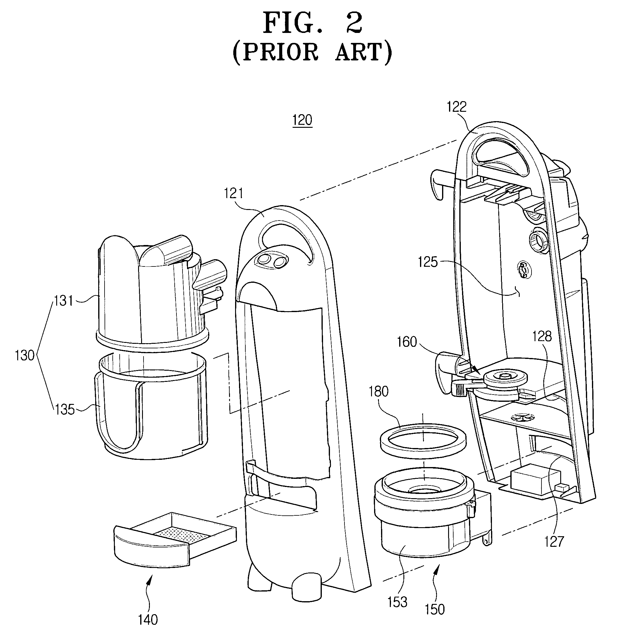
Also, in situations where the airflow path is provided to connect the motor assembly 150 and the auxiliary filter assembly 140, since noise occurs during operation in the connection portions of the airflow path and the motor assembly 150 and the auxiliary filter assembly 140, there is a problem that a user cannot enjoy a quiet cleaning work.
Furthermore, due to the addition of the extra airflow path and the sealing device, a manufacturing process of the vacuum cleaner 100 becomes more complicated and a manufacturing cost is increases.
Thus, a heretofore unaddressed need exists in the industry to address the aforementioned deficiencies and inadequacies.

Method used


Image

  • Motor assembly and vacuum cleaner having the same
  • Motor assembly and vacuum cleaner having the same
  • Motor assembly and vacuum cleaner having the same

Examples


Embodiment Construction

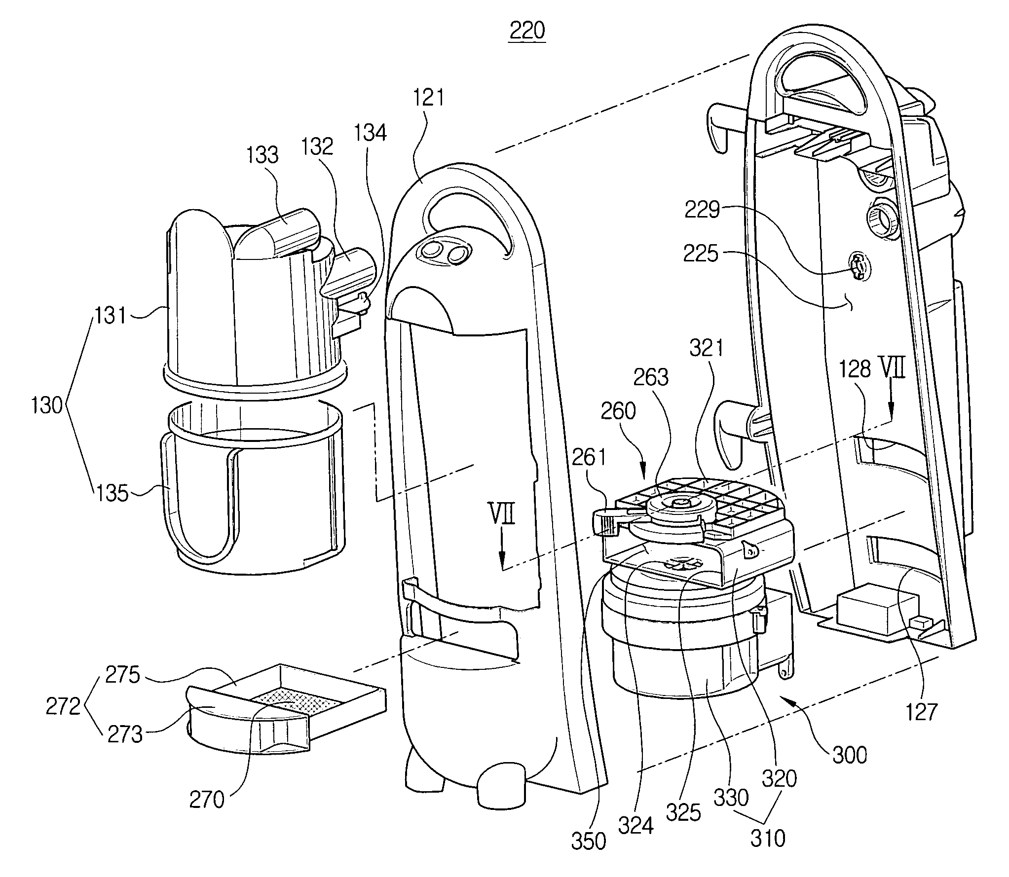
[0028]Hereinafter, a preferred embodiment of the present invention will be described in greater detail with reference to the accompanying drawings. With respect to the elements identical to those of the conventional vacuum cleaner as shown in FIGS. 1 and 2, like reference numerals are assigned.

[0029]Referring to FIGS. 3-7, a vacuum cleaner according to a preferred embodiment of the present invention includes a cleaner body 220, a cyclone dust-collecting apparatus 130, and a motor assembly 300. As shown in FIG. 3, the cleaner body 220 includes a dust-collecting chamber 225 with a discharge opening 127. The motor assembly 300 is disposed in the cleaner body 220. Accordingly, external air drawn in from outside through a dirt-suctioning opening (not shown) of a suction assembly 110 (see FIG. 1) sequentially passes through the dust-collecting chamber 225 and the motor assembly 300, and is discharged out of the cleaner body 220 through the discharge opening 127.

[0030]The cyclone dust-coll...


PUM

PropertyMeasurementUnit
suction forceaaaaaaaaaa
distanceaaaaaaaaaa
centrifugal forceaaaaaaaaaa

Abstract

A motor assembly for a vacuum cleaner for providing a user with a quieter environment during a cleaning work, and a vacuum cleaner having the same, is disclosed. The motor assembly includes a motor generating a suction force, an auxiliary filter member disposed on an airflow path connecting the motor to a dust-collecting apparatus for filtering a second time the air discharged from the dust-collecting apparatus, and a motor casing. The motor casing includes a first chamber connected to the dust-collecting apparatus with the auxiliary filter member mounted therein. A second chamber is connected to a discharge opening of the cleaner body and includes the motor mounted therein. A connection path is in fluid communication with the first chamber and the second chamber.

Description

REFERENCE TO RELATED APPLICATION[0001]This application claims priority to copending Korean Patent Application No. 2003-45759, filed on Jul. 7, 2003, in the Korean Intellectual Property Office, the disclosure of which is entirely incorporated herein by reference.CROSS REFERENCE TO RELATED APPLICATIONS[0002]This application is related to copending applications entitled “Dust Collecting Apparatus For Cyclone Type Vacuum Cleaner”, (Korean Application 10-2003-0012029, filed Feb. 26, 2003), “Cyclone-Type Dust Collecting Apparatus For Vacuum Cleaner”, (Korean Application 10-2002-0077811, filed Dec. 9, 2002), and “Cyclone Type Dust Collecting Apparatus of Vacuum Cleaner”, (Korean Application 10-2003-0033167, filed May 24, 2003) which disclosures are commonly owned by the same assignee as the present application and are entirely incorporated herein by reference.FIELD OF THE INVENTION[0003]The present invention relates to a vacuum cleaner, and more particularly, to a motor assembly disposed i...

Claims


Application Information

Patent Timeline
Patent Type & Authority Patents(United States)
IPC IPC(8): A47L9/16A47L5/30A47L9/00A47L9/12A47L9/22
CPCA47L9/0081A47L9/22A47L9/122Y10S55/03A47L5/28A47L9/00A47L9/10
Inventor PARK, JUNG-SEON
Owner SAMSUNG GWANGJU ELECTRONICS CO LTD
Learn More