Plant marker

a plant marker and marker technology, applied in the field of markers, can solve the problems of inability to adapt to the use of different species of plants, inconvenient cleaning, if not difficult, etc., and achieve the effect of not being able to easily remove the two parts in a sudden manner

Active Publication Date: 2007-10-02
KINCAID GARDENS
View PDF12 Cites 9 Cited by
  • Summary
  • Abstract
  • Description
  • Claims
  • Application Information

AI Technical Summary

Benefits of technology

[0009]It is, therefore, an object of the present invention to provide a plant marker assembly that allows for different plant identifying components to be used interchangeably with a single ground anchoring component.
[0011]Finally, it is yet another object of the present invention to provide a plant marker of a configuration which is sufficiently aerodynamic to resist being toppled by wind gusts. In fact, by employing a stake constructed of wire and a display member that sits inclined upon the stake, the marker presents minimal surface area that is exposed to wind.

Problems solved by technology

However, a drawback of many unitary prior art markers is that they are not adapted for use in identifying different species of plants.
However, because the pocket parts of many of these types of assemblies can be constantly exposed to the environment, they often are susceptible to mold formation or corrosion that can affect transparency of the material through which a pocketed sign or other form of plant indicia is to be viewed.
Furthermore, particularly because of their size dimensions, these holding spaces can be inconvenient, if not difficult, to clean.
Thus, when a plant identification part of a marker assembly becomes deteriorated or otherwise undesirable, a consumer need only replace that identification part and not the stake part.
Nevertheless, despite this advantage, depending upon specifically how a removable identification part of a plant marker is to be affixed to the stake part (i.e., by friction therebetween, a locking mechanism, etc.), there may exist the possibility of the two parts becoming inadvertently detached, especially due to wind effects or extensive wear.

Method used


Image

  • Plant marker
  • Plant marker
  • Plant marker

Examples


Embodiment Construction

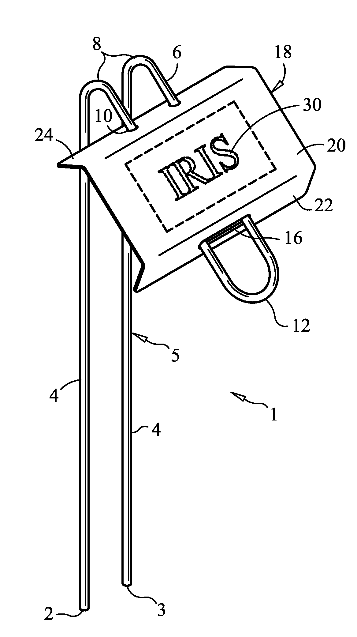
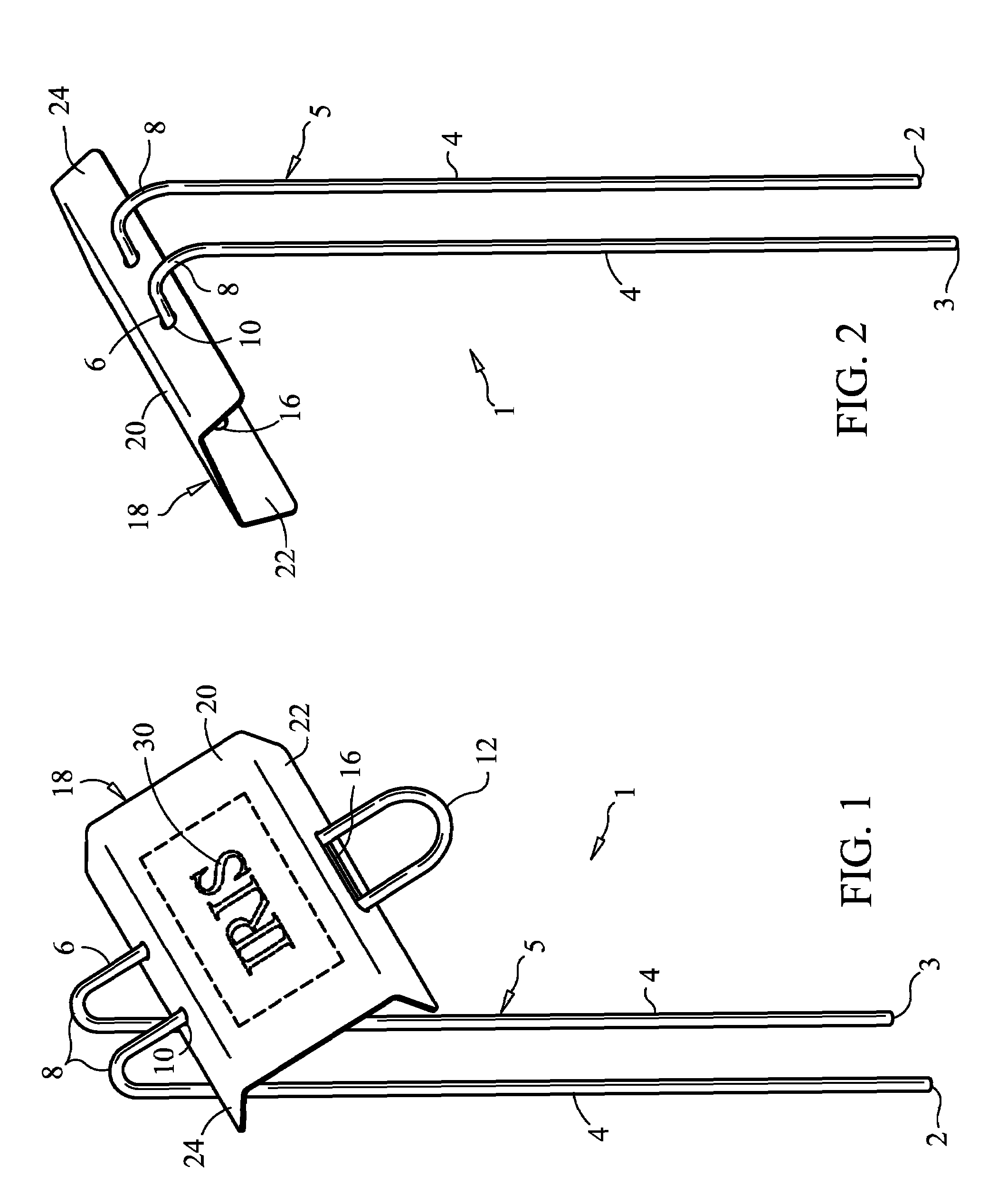
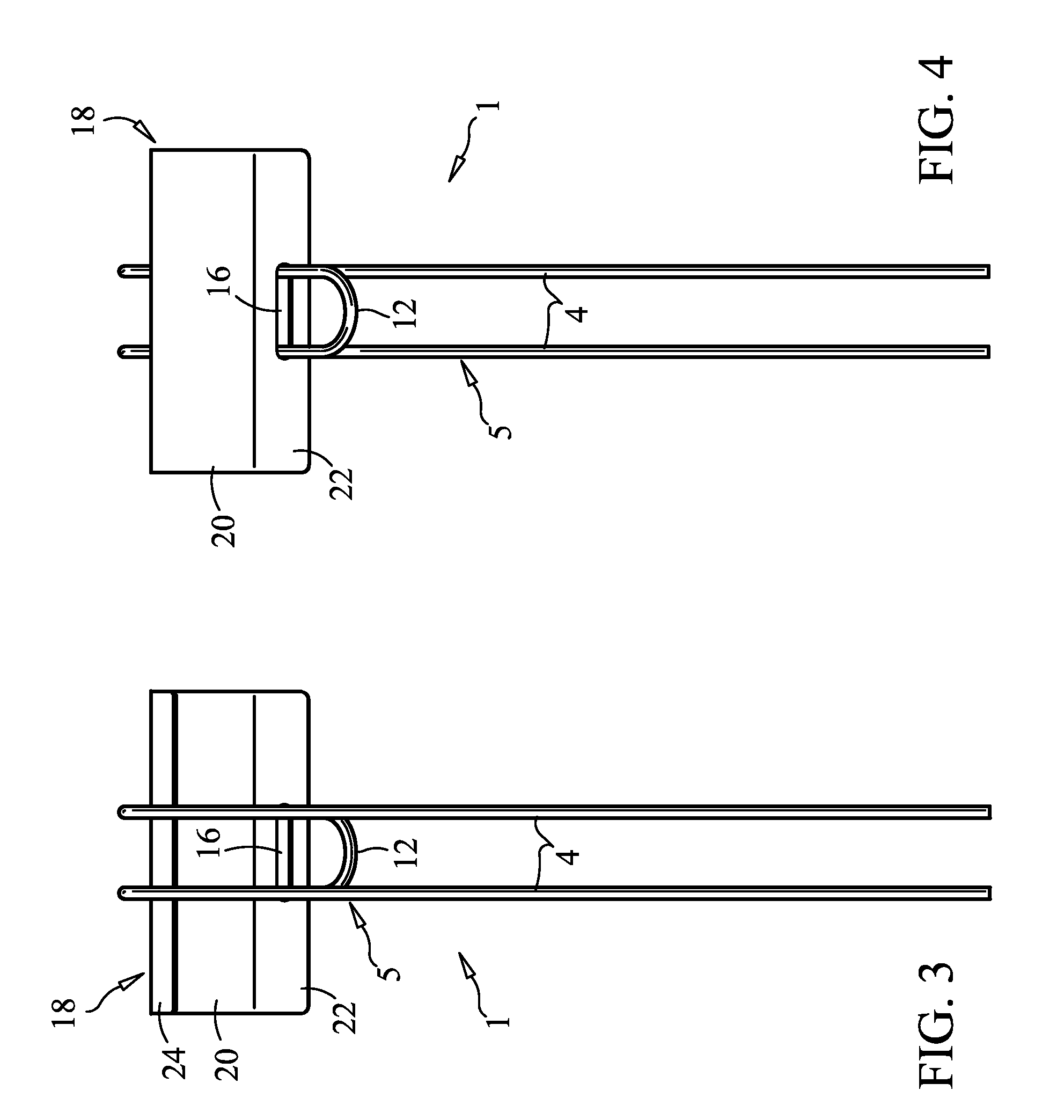
[0021]A preferred embodiment of the plant marker of the present invention is best illustrated in FIGS. 1 and 9. Such an embodiment of the marker 1 is comprised of three assembled elements: a ground stake 5, a display plate 18 and identifying indicia 30.

[0022]The stake 5 is a wire rod constructed of a rust resistant material such as aluminum, stainless steel, zinc or molded hard plastic. Midway between the wire's two ends 2, 3 is a semicircular bend 12 which separates the stake wire into two legs. Along the legs, approximately one-third of the distance from the aforementioned bend 12 to the respective leg ends 2, 3, are a pair of symmetrical bends 8. These bends 8 effectively subdivide the stake 5 into a plate mounting portion 6 and a ground anchoring portion 4. Preferably, the distal bends 8 put the mounting portion 6 and anchoring portion 4 in approximately 45-degree relation to each other. This angled configuration allows persons to view the display from a horizontal distance whil...


PUM


Abstract

A plant or garden marker assembly comprising a ground stake element, preferably constructed of rigid metal wire, and an identification plate element, preferably fabricated of sheet metal. A decal is applied to a flat portion of the plate for purposes of plant identification. Flanged front and rear sections of the plate feature holes through which the stake is threaded to enable the plate to be friction mounted thereupon. The plate may also be detached from the stake, allowing a single stake to be used with different plates displaying various plant identifications.

Description

[0001]This application claims the benefit of the filing of application 29 / 246,627.BACKGROUND OF THE INVENTION[0002]The present invention generally relates to a marker, and it is specifically directed an improved plant marker assembly comprised of a ground stake element and a detachable identification plate element.[0003]The prior art is replete with apparatuses that are driven into the ground for the purpose of identifying plants and vegetation growing within their vicinity. Some of these known plant markers are simply single piece articles comprising both ground anchoring and plant identification sections. U.S. Pat. No. D483,410 to Overdevest, et al., for example, illustrates a plant identification marker of such singular construction. However, a drawback of many unitary prior art markers is that they are not adapted for use in identifying different species of plants. More specifically, when a marker's anchoring part is inseparably integrated with its plant indicia-bearing part, th...

Claims


Application Information

Patent Timeline
Patent Type & Authority Patents(United States)
IPC IPC(8): A47G7/00
CPCG09F3/12G09F3/206G09F7/18
Inventor KINCAID, GARY L.
Owner KINCAID GARDENS
Why Eureka
Try Eureka