
Electronics housing with standard interface

a technology of electronic housing and interface, applied in the direction of hermetically sealed casings, electrical apparatus casings/cabinets/drawers, printed circuit non-printed electric components association, etc., can solve the problems of fatigue in the sealing material, and achieve good diffusion resistance to aggressive chemicals, increase long-term stability, and increase rigidity

Inactive Publication Date: 2014-03-18
CONTINENTAL AUTOMOTIVE GMBH
View PDF37 Cites 2 Cited by
  • Summary
  • Abstract
  • Description
  • Claims
  • Application Information

AI Technical Summary

Benefits of technology

[0015]A flexible printed circuit board having conductor tracks that is known per se can be used as the electrical connection. Equally, however, one or more partial flexible printed circuit boards in accordance with the arrangement described in DE 10 2004 036 683 A1 can be used. An advantageous aspect of this exemplary embodiment is to prepare individual partial flexible printed circuit boards in such a way that the contacting means to the open areas of the conductor tracks for individual component types can already be taken into account and standardized at this early stage in the fabrication of an individual component. Furthermore this embodiment variant fulfills the further advantageous parameters of keeping the overall surface area of the flexible printed circuit boards to a minimum, in particular for cost reasons. This embodiment of the invention also permits an optimal separation of the signal and current paths.
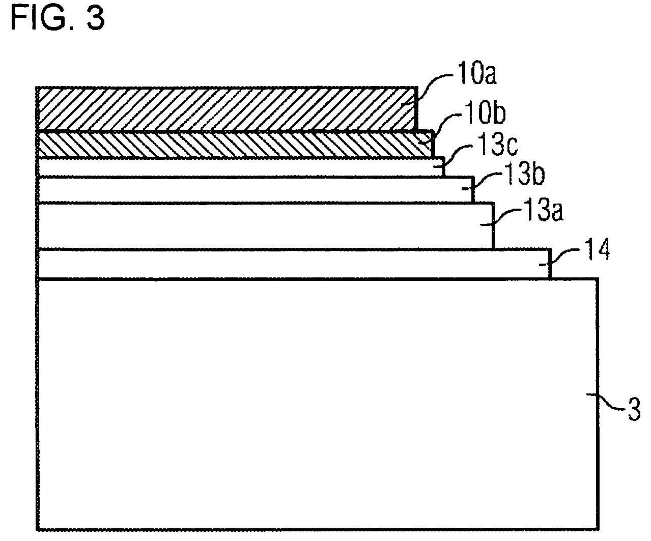
[0017]Alternatively, the top polyimide cover film can also be completely or partially omitted, provided the area not covered by the top polyimide cover film is protected from external influences by other component parts of the inventive housing, such as, for example, by the housing lid and / or by contacting covers. Further, preferably more economical, materials can also be used both for the base film and for the adhesive layer. Thus, for example, materials of a kind which can be applied using a spraying, varnishing or screen-printing method can be provided in order to reduce costs. In addition it is possible to vary the layer thickness of the individual layers.
[0020]The housing base preferably consists of a metallic material; particularly preferably it is made of aluminum. In a preferred embodiment of the invention the flexible printed circuit board is laminated onto the metallic housing base. This ensures a reliable, hermetically sealed and low-cost fixing. The housing lid can consist of any material that ensures adequate protection of the electronics against the given environmental conditions. In addition to housing lids made of plastic, lids made of metallic materials can also be used. If the intention is to fix the housing lid in place by means of soldering, a housing lid made of metal should preferably be provided. At the same time this provides the necessary EMC shielding values and an increased rigidity. Alternatively a metalized plastic molded body can also be used. In an advantageous embodiment, however, the housing lid is manufactured from a metallic material such as, for example, sheet steel or die casting. This results in increased long-term stability, good diffusion resistance toward aggressive chemicals, and improved shielding values over the entire lifespan of the control device.
[0023]Connections between electronic components disposed outside the housing and the electronic connection of the present invention can be established in any known manner. Thus, the connections can be produced as detachable, for example as plug-in connectors, or non-detachable by means of, for example, soldering, welding, or crimping. Particularly preferably, the electronic connection is directly connected both to the electronic substrate in the interior of the housing and to the signal transmitters and receivers (in particular sensors, valves, etc.) disposed outside of the housing, and it is particularly preferred if the means used is thick-wire bonding. This enables the number of connections to be significantly reduced and in this way part failures due to defective interfaces such as e.g. connectors can be avoided. Proneness to faults is reduced considerably thereby.

Problems solved by technology

The disadvantage of this arrangement is that it is necessary to manufacture the housing components specifically for each control device because of the molded-in or press-fitted electrical connections.
Moreover, signs of fatigue in the sealing material can become apparent over the course of the lifetime of a control device of said kind, in particular in an extremely aggressive environment such as in the case of transmission control devices which are surrounded by chemically highly corrosive transmission fluid and at the same time are required to withstand high temperatures.
In these instances too, however, there exists in each case the disadvantage that for each control device it is necessary to manufacture an individually tailored layout geared to the components involved for the housing and the geometry of the flexible printed circuit boards.

Method used


Image

  • Electronics housing with standard interface
  • Electronics housing with standard interface
  • Electronics housing with standard interface

Examples


Embodiment Construction

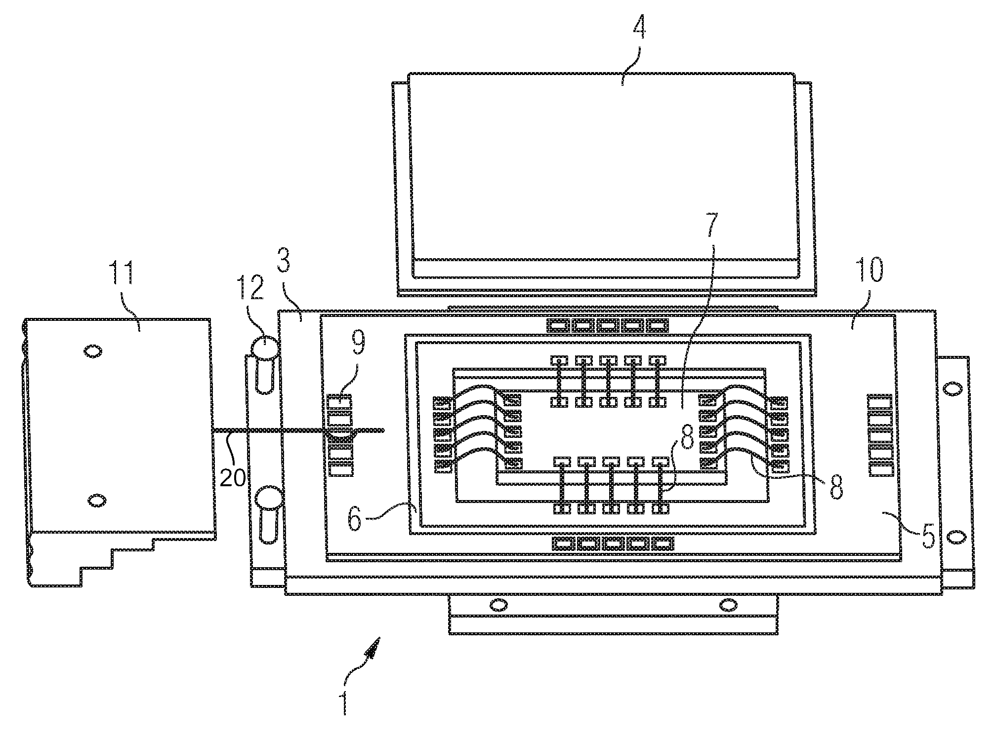
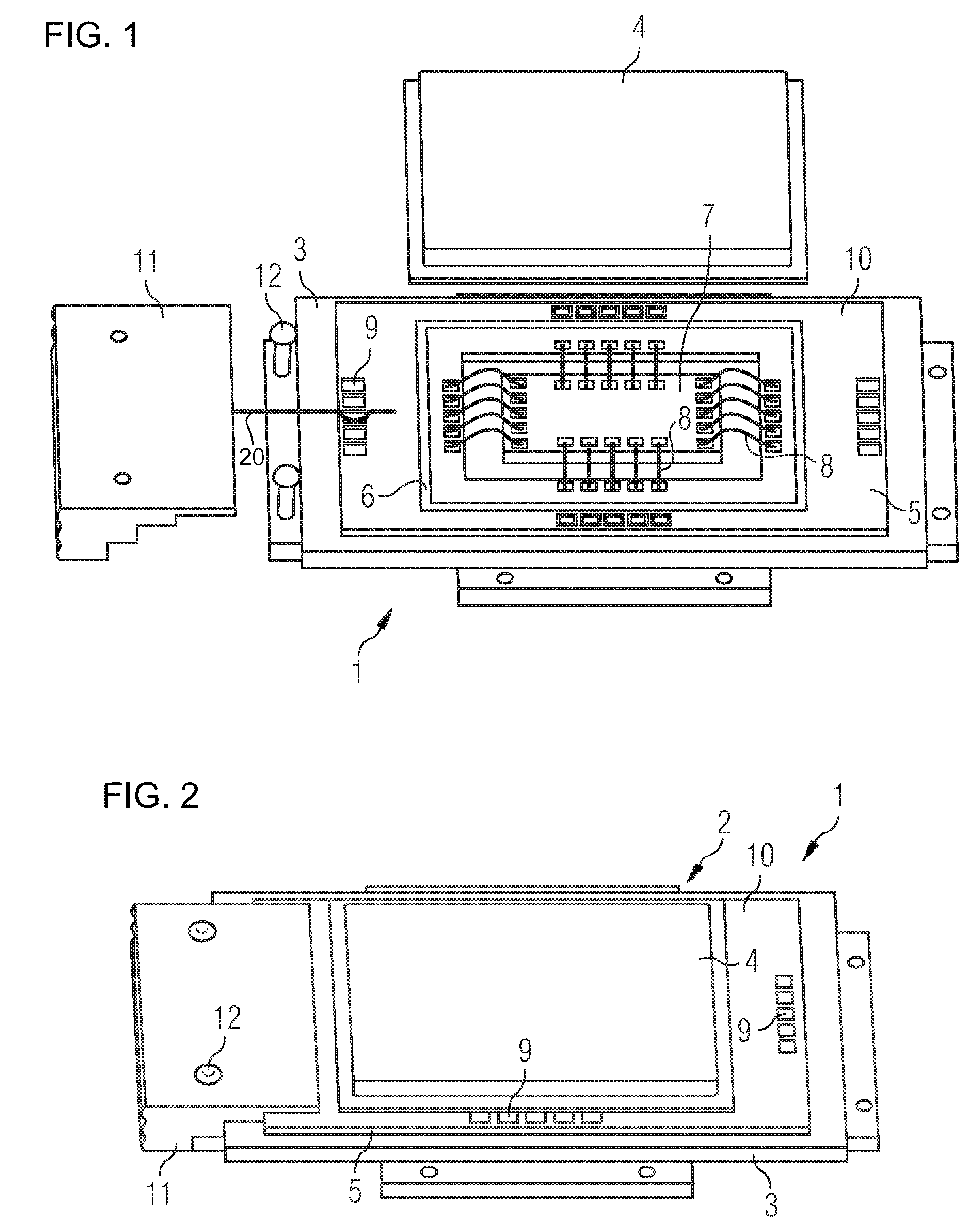
[0032]FIG. 1 shows an electronic device 1 which is provided for installation in a motor vehicle transmission. The housing 2 of the electronic device is formed from a metallic baseplate 3 and a housing lid 4 made of sheet steel or aluminum. A flexible printed circuit board 5 is fixed on the metallic baseplate 3. Around its perimeter the printed circuit board 5 has a sealing zone 6 which corresponds in shape to the contact surface of the housing lid 4. Inside the housing is an electronic substrate 7 which can have different electronic components for example. The substrate 7 with its different electronic components in the interior of the housing is connected to the flexible printed circuit board 5 via direct contacts 8. Furthermore the flexible printed circuit board 5 shown is cut out in the interior of the housing and the electronic substrate 7 is disposed in the cutout thus produced. In its edge zones the flexible printed circuit board 5 has contacting points 9 for directly contactin...


PUM

PropertyMeasurementUnit
temperatureaaaaaaaaaa
lengthaaaaaaaaaa

Abstract

A housing for an electronic control device includes at least two housing parts, at least one housing base, a housing lid and an electronic connection between components disposed inside the housing and components disposed outside the housing. The connection is fixed to the base of the housing. The electronic connection is either constructed as a single-component flexible printed circuit board or as at least one partial flexible printed circuit board including at least one uniform open area of a copper conductor track outside an area covered by the housing lid. The width of the uniform region is oriented to a predefined contacting type of peripheral components and is longer than necessary for the contacting type. The invention therefore provides for a variable adaptation of generic electronics housings, thereby not necessarily requiring a novel structure of the housing with corresponding expensive individual packaging.

Description

BACKGROUND OF THE INVENTION[0001]1. Field of the Invention[0002]The invention relates to an electronics housing for an electronic control device according to the preamble of claim 1 as well as to a method for manufacturing a housing of said type, in particular for transmission controls or engine management systems in the automobile industry.[0003]Electronic control devices generally have a plurality of electronic components which are connected to other components disposed outside the control device. Normally they are installed in special housings or enclosures in order to protect them against environmental influences or mechanical stresses. In addition the housings fulfill an important shielding function. In order to allow a reliable connection to components located outside the housing, an electrical connection from the housing interior to the housing exterior is necessary.[0004]2. Prior Art[0005]DE 10 2004 033 559 A1 describes a connection of said type which is arranged between the...

Claims


Application Information

Patent Timeline
Patent Type & Authority Patents(United States)
IPC IPC(8): H05K5/00
CPCH01L2224/48472H05K1/189H01L2924/3025H05K1/118H05K3/0061H05K5/0082H01L2224/49175H05K2201/0989H05K2203/1147H05K1/147H01L2224/48091H05K1/142H05K2201/09954H05K2203/049H01L2224/05553Y10T29/4913H01L2924/00014H01L2924/00
Inventor LOIBL, JOSEFSMIRRA, KARL
Owner CONTINENTAL AUTOMOTIVE GMBH
Learn More