
Method for manufacturing a heat pipe having an enlarged portion

Inactive Publication Date: 2007-10-02
CHAUN CHOUNG TECH
View PDF3 Cites 4 Cited by
  • Summary
  • Abstract
  • Description
  • Claims
  • Application Information

AI Technical Summary

Benefits of technology

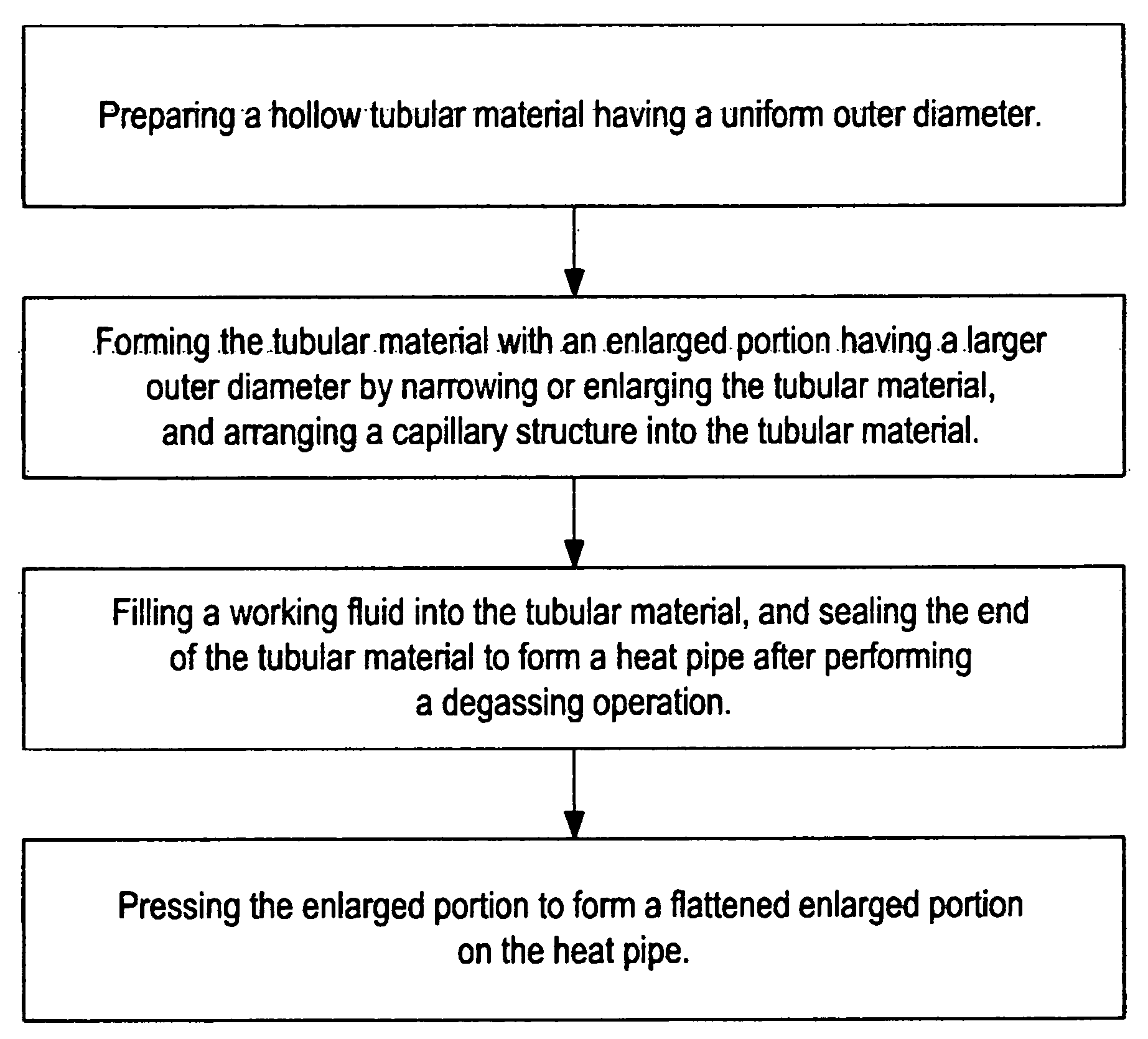
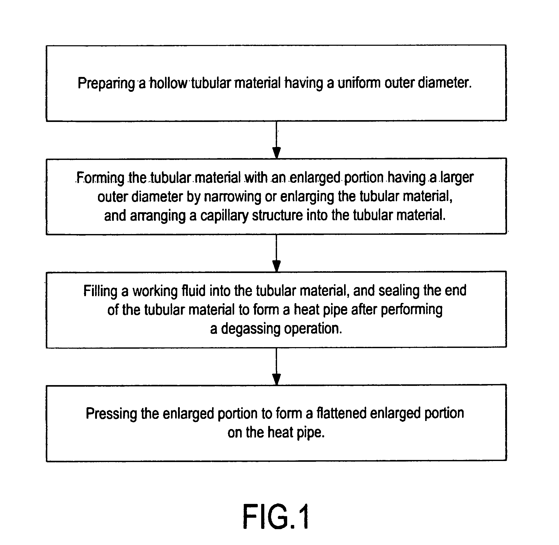
[0006]The present invention is to provide a method for manufacturing a heat pipe having an enlarged portion, characterized in that: before being formed into a heat pipe, a hollow tubular material having a uniform outer diameter is formed with an enlarged portion having a larger outer diameter by narrowing or enlarging the tubular material; when the tubular material is filled with a working fluid and formed into a heat pipe after performing a degassing operation, the heat pipe is made to have an enlarged portion with a larger outer diameter; after pressing the heat pipe, a larger surface area can be obtained, so that the heat pipe is more suitable for contacting with the heat-conducting plate or the electronic heat-generating element.

Problems solved by technology

However, since in most cases the outer diameter of the original heat pipe is 8 mm, the surface area of the flattened section after pressing is not large enough.

Method used


Image

  • Method for manufacturing a heat pipe having an enlarged portion
  • Method for manufacturing a heat pipe having an enlarged portion
  • Method for manufacturing a heat pipe having an enlarged portion

Examples


Embodiment Construction

[0019]In order to make the Examiner better understanding the characteristics and the technical contents of the present invention, a detailed description will be made with reference to the accompanying drawings. However, it should be understood that the drawings are illustrative but not used to limit the scope of the present invention.

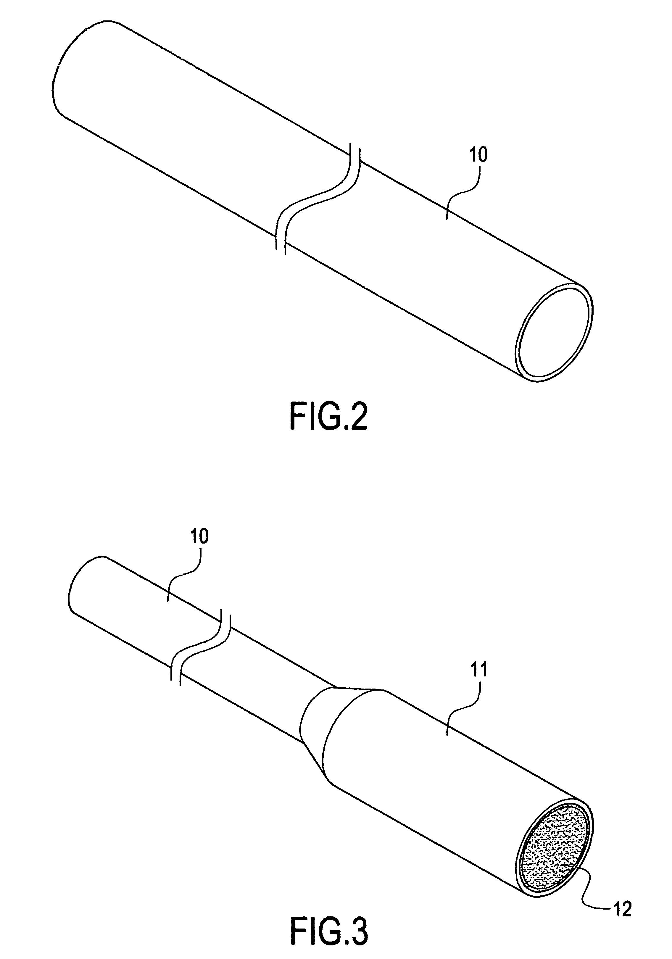
[0020]With reference to FIGS. 1 and 6, FIG. 1 is a schematic flow chart of the present invention, and FIG. 6 is a schematic view showing the operating state of the heat pipe manufactured by the present invention. The present invention provides a method for manufacturing a heat pipe having an enlarged portion and comprises the following steps.[0021]a) As shown in FIG. 2, a hollow tubular material 10 having a uniform outer diameter is prepared. The tubular material 10 can be a copper pipe and formed into a pipe having a uniform outer diameter by drawing. Further, the drawn pipe is cut into sections according to the desired length. After washing and cleani...


PUM

PropertyMeasurementUnit
Capillary waveaaaaaaaaaa
Diameteraaaaaaaaaa

Abstract

A method for manufacturing a heat pipe having an enlarged portion includes the steps of: preparing a hollow tubular material having a uniform outer diameter; forming the tubular material with an enlarged portion having a different or larger outer diameter by narrowing or enlarging the tubular material; arranging a capillary structure into the tubular material; filling a working fluid into the tubular material after sealing one end of the tubular material; sealing the end to form a heat pipe after performing a degassing operation; and pressing the enlarged portion obtained in the previous step to form a flattened enlarged portion on the heat pipe.

Description

BACKGROUND OF THE INVENTION[0001]1. Field of the Invention[0002]The present invention relates to a method for manufacturing a heat pipe having an enlarged portion. Especially, the present invention aims to manufacture a tubular heat pipe, thereby to increase the contacting area between the heat pipe and a heat-conducting plate or an electronic heat-generating element.[0003]2. Description of Prior Art[0004]In a conventional tubular heat pipe, the condensed end thereof is usually connected to a plurality of heat-dissipating fins, and the heated end thereof is brought into contact with a heat-conducting plate or an electronic heat-generating element. In terms of the performance of heat transfer, the heated end should be brought into contact with the heat-conducting plate and the electronic heat-generating element as much as possible to increase the contacting area. Therefore, traditionally, the tubular heat pipe is directly made flattened by performing a pressing process for subsequent...

Claims


Application Information

Patent Timeline
IPC IPC(8): B21D26/02
CPCB21D22/025F28D15/0283B21D26/033Y10T29/49353
Inventor WU, CHUNGHUANG, MENG-CHENGWANG, TONY
Owner CHAUN CHOUNG TECH
Learn More