One-way plastic pallet

Inactive Publication Date: 2007-10-02
SHUERT TECH
View PDF20 Cites 31 Cited by
  • Summary
  • Abstract
  • Description
  • Claims
  • Application Information

AI Technical Summary

Benefits of technology

[0007]According to the invention, the leg structures are formed of spaced downstanding leg portions of the upper sheet fused in vertically overlapping relation to spaced upstanding leg portions of the lower sheet and main body planar portions of the upper sheet between the spaced downstanding leg portions coact with main body planar portions of the lower sheet between the spaced upstanding leg portions to define the forklift passages. This arrangement allows the provision of an inexpensive pallet with adequate leg structures and well defined forklift passages.
[0008]According to a further feature of the invention, the lower sheet further includes an upstanding flange portion extending around the perimeter of the lower sheet and fused to the perimeter of the upper sheet, and openings are provided in the flange portion, in alignment with the forklift passages, to provide forklift access to the forklift passages. This arrangemen

Problems solved by technology

For example, they are subject to breakage and they take up a considerable amount of valuable floor space in the warehouse when they are not in use.
They are also difficult to maintain in a sanitary condition, thus limiting their usability in applications where sanitation is important, for example, in food handling application.
Whereas these twin sheet plas

Method used


Image

  • One-way plastic pallet
  • One-way plastic pallet
  • One-way plastic pallet

Examples


Embodiment Construction

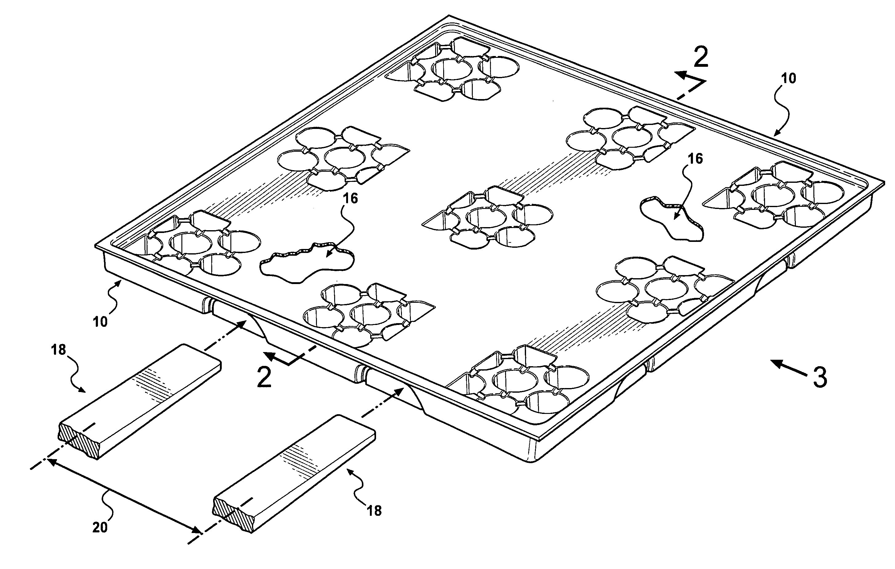
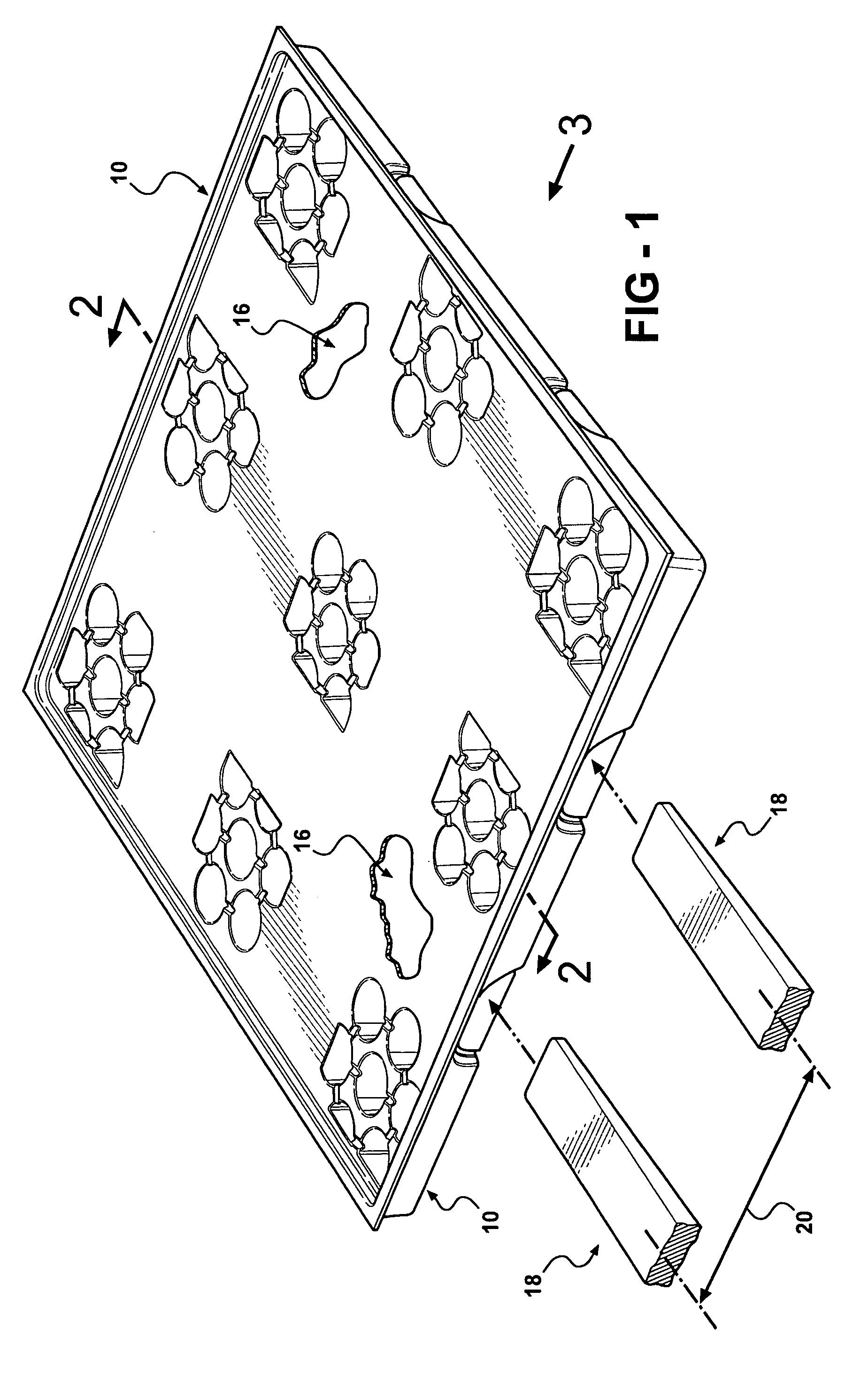
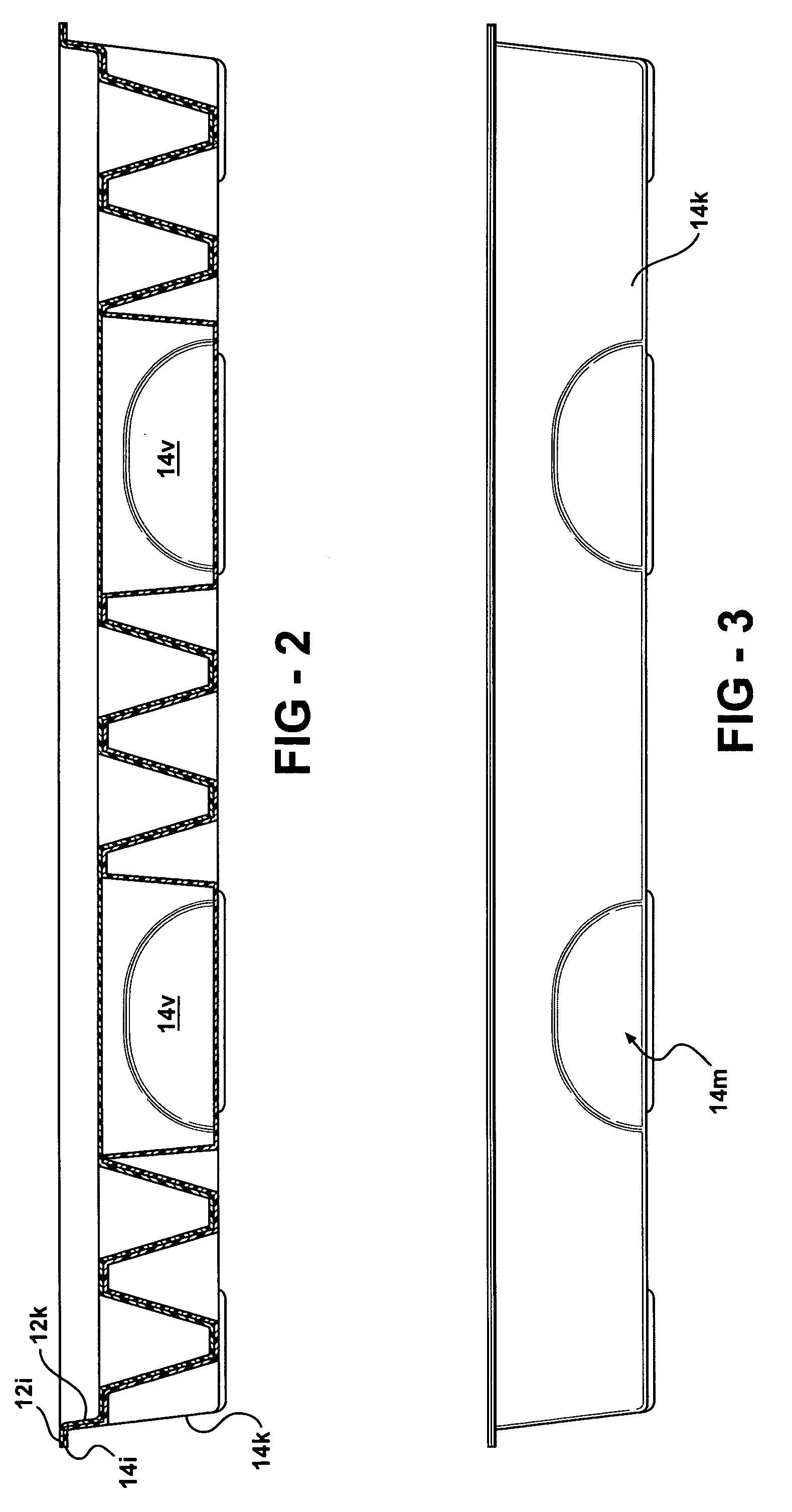
[0025]The pallet 10 of the invention, broadly considered, comprises an upper plastic sheet 12 and a lower plastic sheet 14. Sheets 12 and 14 are preferably formed of a polyethylene material and may have a thickness of approximately 0.070 inches. In overview, each sheet is formed in a vacuum thermoforming operation and the upper and lower sheets, while still in a heated fuseable condition, are brought together to selectively fuse portions of the upper sheet to portions of the lower sheet to form the pallet.

[0026]Upper sheet 12 has a generally rectangular configuration and includes leg portions 12a-12i and planar main body portions 12j between the leg portions. Sheet 12 also includes an upstanding flange 12k extending around the periphery of the sheet and terminating in an outwardly extending lip 12i.

[0027]Each leg portion 12a-12i is constituted by a cluster of downwardly extending hollow protrusions 12m. Each protrusion has a circular transverse cross-section and a frusto conical ve...


PUM


Abstract

A thermoformed twin sheet pallet comprising an upper plastic sheet and a lower plastic sheet, the sheets being fused together to form a platform structure and a plurality of leg structures downstanding from the platform structure in spaced relation and defining a plurality of forklift passages therebetween. The leg structures are formed of spaced downstanding leg portions of the upper sheet fused in vertically overlapping relation to spaced upstanding leg portions of the lower sheet, and main body planar portions of the upper sheet between the spaced downstanding leg portions coact with main body planar portions of the lower sheet between the spaced upstanding leg portions to define the forklift passages. The lower sheet further includes an upstanding flange portion extending around the perimeter of the lower sheet and fused to the perimeter of the upper sheet and openings are provided in the flange portion, in alignment with the forklift passages, to provide forklift access to the forklift passages. A flap is provided in each opening which is yieldable to allow entry of a forklift into the opening for access to the respective forklift passage. The downstanding leg portions of the upper sheet comprise clusters of hollow protrusions opening in the upper face of the upper sheet and the upstanding leg portions of the lower sheet comprise clusters of hollow protrusions opening in the lower face of the lower sheet and including sidewalls fused to sidewalls of the downstanding protrusions of the upper sheet.

Description

FIELD OF THE INVENTION[0001]This invention relates to shipping and storage pallets and more particularly to pallets having a plastic construction.BACKGROUND OF THE INVENTION[0002]Pallets have traditionally been formed of wood. Wood pallets however have many disadvantages. For example, they are subject to breakage and they take up a considerable amount of valuable floor space in the warehouse when they are not in use. They are also difficult to maintain in a sanitary condition, thus limiting their usability in applications where sanitation is important, for example, in food handling application.[0003]In an effort to solve some of the problems associated with wood pallets, plastic pallets have been employed with some degree of success. In one generally successful form of plastic pallet design, a twin sheet construction has been used in which upper and lower plastic sheets are formed in separate molding operations and the two sheets are then selectively fused or knitted together in a s...

Claims


Application Information

Patent Timeline
IPC IPC(8): B65D19/38
CPCB65D19/0018B65D2519/00034B65D2519/00069B65D2519/00273B65D2519/00562B65D2519/00318B65D2519/00338B65D2519/00407B65D2519/00412B65D2519/00288
Inventor SHUERT, LYLE H.
Owner SHUERT TECH
Why Eureka
Try Eureka