Adjustable combination propulsion and control handle for a work machine

a combination, work machine technology, applied in the direction of manual control with single controlling member, mechanical control devices, instruments, etc., can solve the problems of difficult operation of multi-directional switches such as dome switches, toggle switches, paddle switches, and require precise and complex fine motor finger manipulations, so as to optimize the fine motor movement of a finger or finger, and eliminate possible twisting or other deformation.

Active Publication Date: 2007-10-02
BLUE LEAF I P INC
View PDF17 Cites 13 Cited by
  • Summary
  • Abstract
  • Description
  • Claims
  • Application Information

AI Technical Summary

Benefits of technology

[0006]According to a preferred aspect of the invention, the combination propulsion and control handle includes an elongate control stalk having a mounting end, a free end opposite the mounting end, and an internal cavity in connection with an opening in the free end. A hand grip is disposed in overlaying relation to at least a portion of the free end of the control stalk, the hand grip including at least one input device in a position so as to be operable by a finger of a hand grasping the hand grip for causing a change of state of the input device. The at least one input device of the hand grip includes at least one elongate conductive element extending therefrom and through the opening and through the internal cavity of the control stalk, the hand grip being mounted so as to allow simultaneous limited rotation thereof about the control stalk and rotation of the at least one elongate conductive element within the stalk. As a result, different operators are able to position his or her hand in a variety of positions and orientations in relation to the control stalk, for such purposes as achieving desired comfort, relieving fatigue, and optimizing fine motor movements of a finger or fingers operating the at least one input device.
[0007]According to another preferred aspect of the invention, a hand rest is mounted about a lower region or portion of the hand grip, so as to extend at least partially therearound for supporting a hand gripping the hand grip, and so as to be rotatable with the hand grip relative to the control stalk. According to another preferred aspect of the invention, the hand grip is retained on the control stalk by at least one retaining element, such as a common fastener such as a screw or the like, a pin such as a roll pin or the like, or other convenient element which passes through the internal cavity of the control stalk and rotates with the hand grip relative to the control stalk, so as to be positioned to contact and urge the conductive element to rotate within the internal cavity when the hand grip is rotated, to eliminate possible twisting or other deformation of the at least one conductive element during the rotation. More preferably, each of the retaining elements extends through a slot in opposite sides of the control stalk so as to support the hand grip in a fixed longitudinal position thereon while allowing the limited rotation of the hand grip about a longitudinal axis through the stalk.
[0008]As another preferred aspect of the invention, a layer of a rubbery material can be disposed between the stalk and the hand grip for providing a limited resistance to rotation of the hand grip relative to the stalk.

Problems solved by technology

This can result in fatigue and discomfort, which can make controlling the machine more taxing and less enjoyable.
Additionally, the operation of multi-directional switches such as dome switches, toggle switches and paddle switches can require precise and complex fine motor finger manipulations, which are made more difficult by fatigue and other conditions resulting from holding one's hand in the same position for long periods of time.
However, if too much movement is allowed, particularly downward movements, the hand may be required to support the hand grip, which can lead to earlier, instead of later, onset of fatigue.
Still further, the locating of multiple input devices on a propulsion handle will typically involve routing a corresponding number of conductive elements such as wires and / or optical cables to the input devices, and allowing a large range of movement of the hand grip may place undesirable stress and strain on the conductive elements.

Method used


Image

  • Adjustable combination propulsion and control handle for a work machine
  • Adjustable combination propulsion and control handle for a work machine
  • Adjustable combination propulsion and control handle for a work machine

Examples


Embodiment Construction

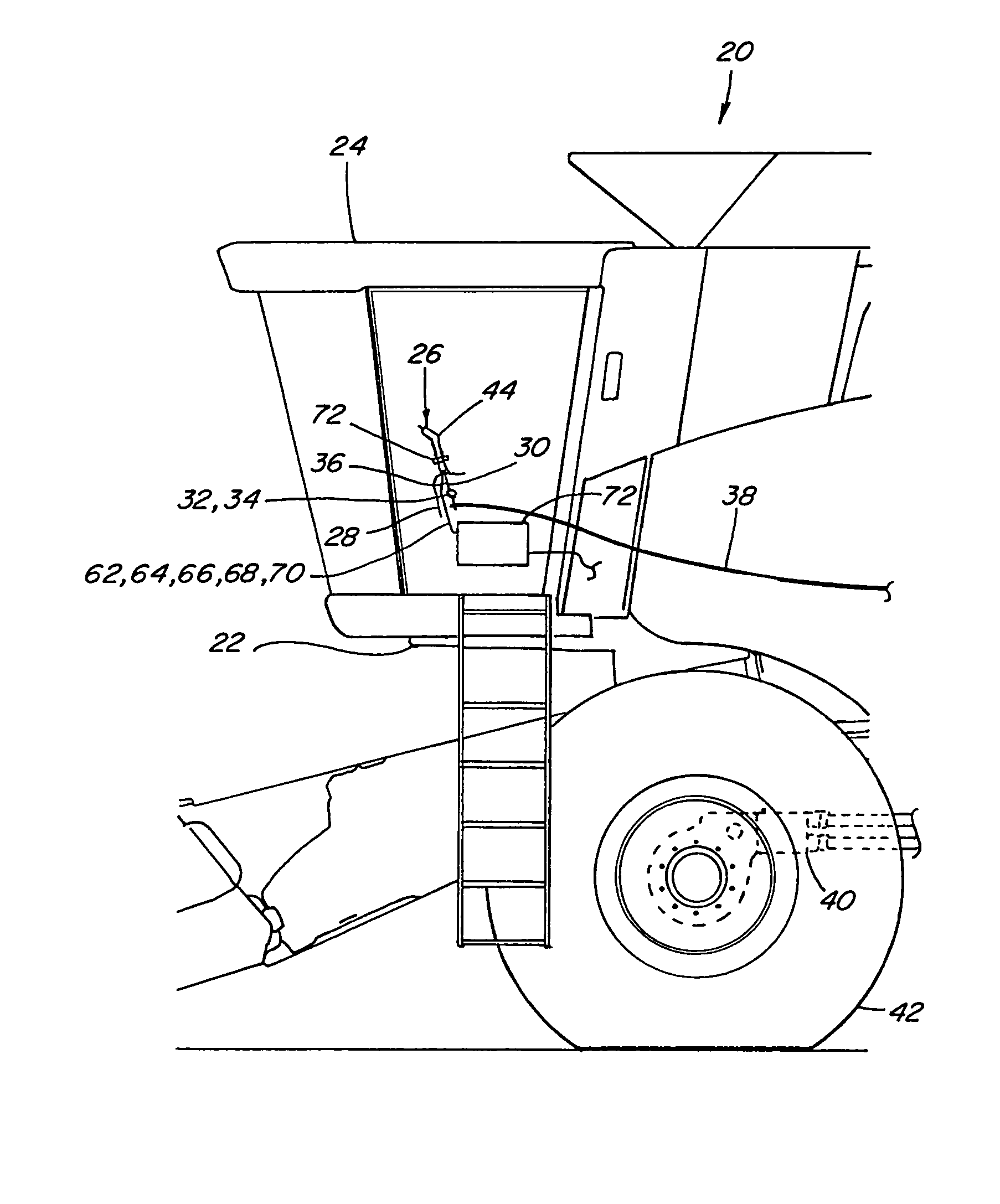
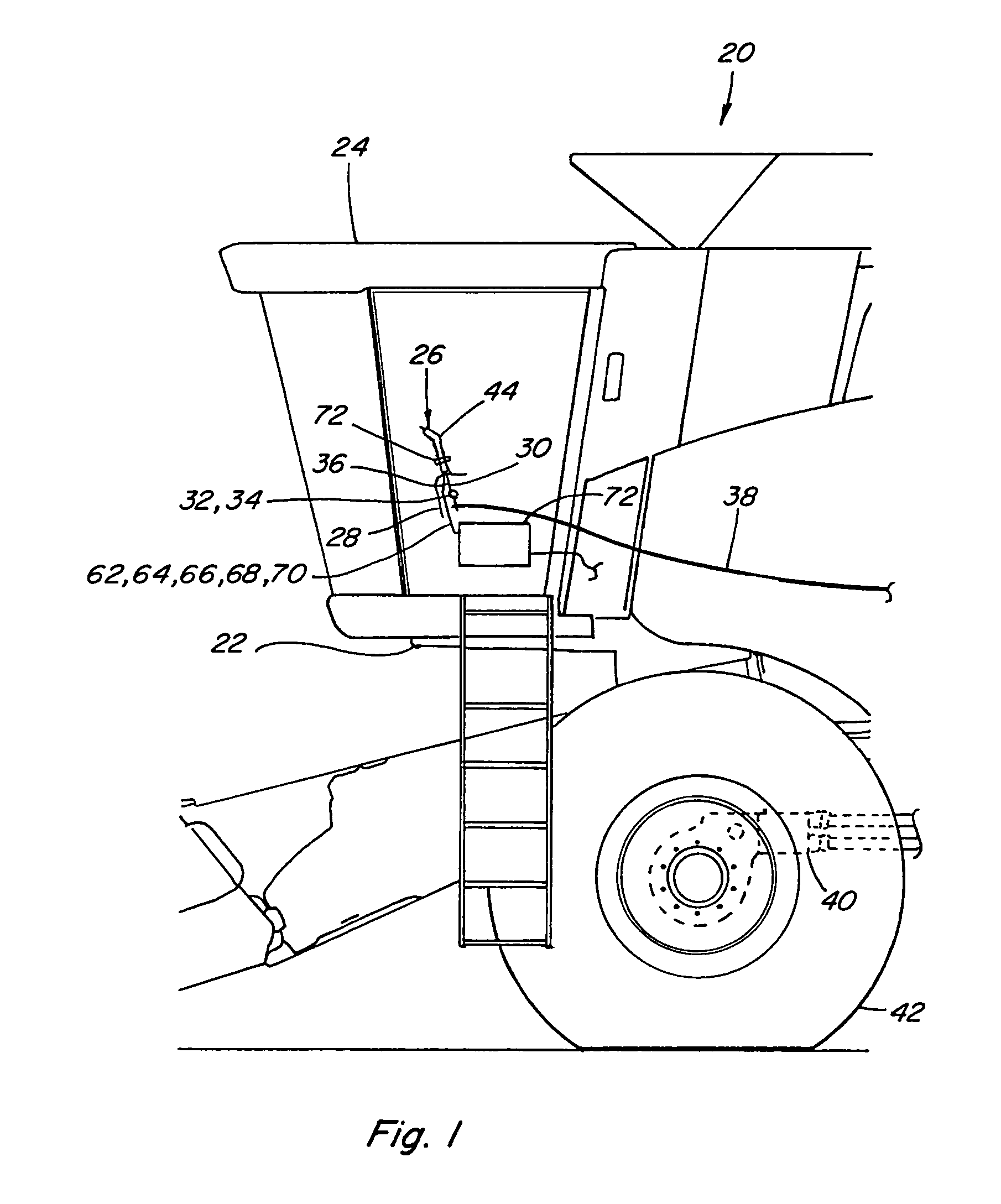
[0023]Referring now to the drawings, wherein a preferred embodiment of the present invention is shown, in FIG. 1, an agricultural combine 20 is shown, including a front end 22 including an operator cab 24 containing a combination propulsion and control handle 26 constructed and operable according to the teachings of the present invention. Combination propulsion and control handle 26 of the invention is shown disposed on a control console 28, which also serves as an arm rest and is located beside an operator seat (not shown) according to a conventional operator cab configuration.

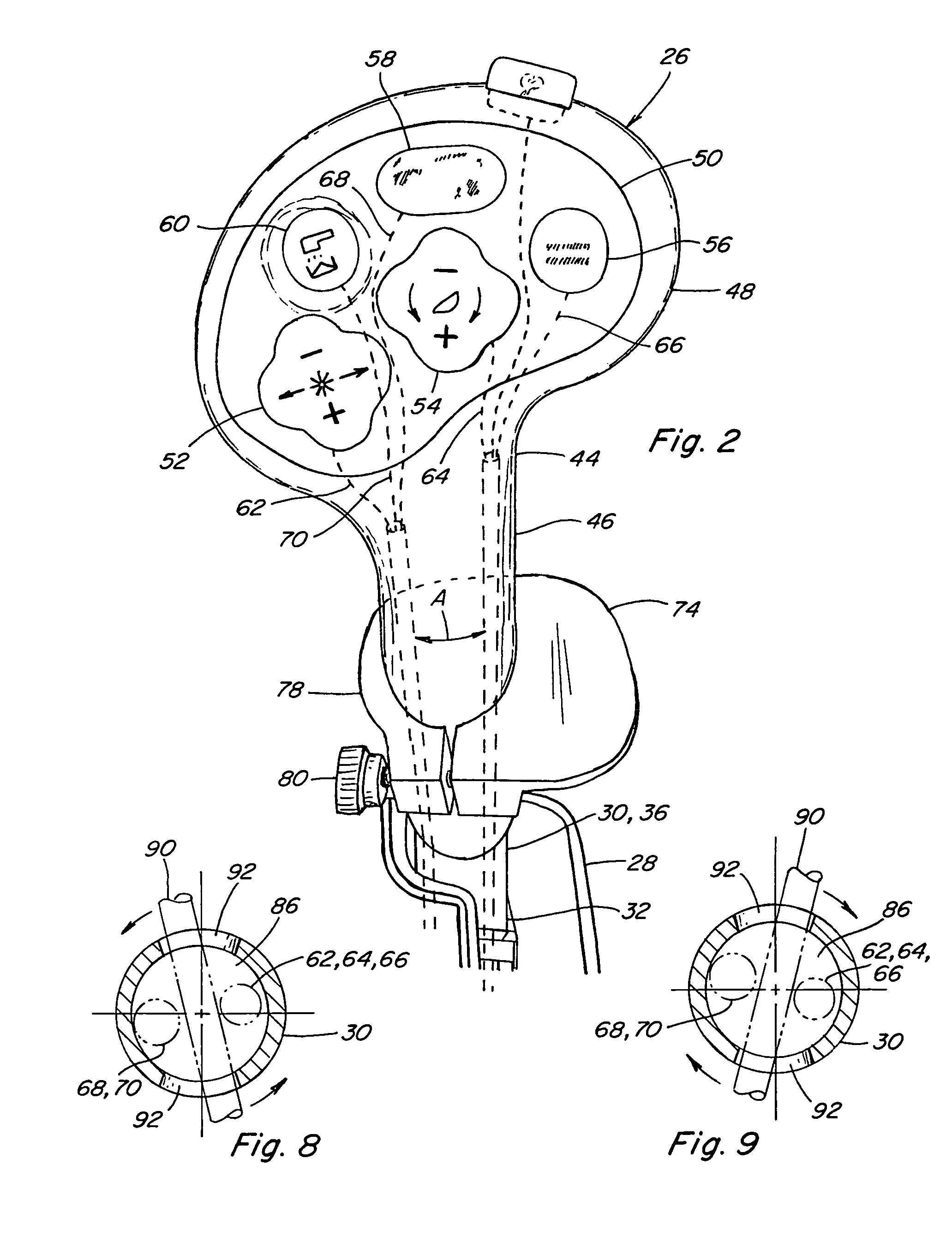
[0024]Combination propulsion and control handle 26 includes an elongate hollow control stalk 30 having a mounting end 32 pivotally mounted at a pivot 34 in connection with console 28, for pivotal movement of an opposite free end 36 of control stalk 30 in a forward and rearward direction, as is well known in the art. Mounting end 32 of control stalk 30 is additionally conventionally connected by a suitable ele...


PUM


Abstract

A combination propulsion and control handle for a work machine, including an elongate control stalk having a mounting end, an opposite free end, and an internal cavity in connection with an opening in the free end, and a hand grip disposed in overlaying relation to the free end, the hand grip including at least one input device in a position so as to be operable by a finger of a hand grasping the hand grip for causing a change of state of the input device, the at least one input device including at least one elongate conductive element extending therefrom through the opening and the internal cavity of the control stalk, the hand grip being mounted so as to allow simultaneous limited rotation thereof about the control stalk and rotation of the elongate conductive element within the stalk, for allowing varying the positioning of an operator's hand, without twisting of the conductive elements.

Description

TECHNICAL FIELD[0001]This invention relates generally to a hand operable propulsion handle of a work machine including at least one finger operable input device thereon for controlling a function of the machine, and more particularly, to combined propulsion handle and machine function control which includes a hand grip portion mounted on an upstanding control stalk, the hand grip being rotatable about the stalk to allow positioning a hand grasping the hand grip in a desired orientation about an axis of the stalk, while maintaining at least one finger of the hand in a position for operating the at least one input device, and without causing strain or significant rubbing or twisting of a conductive element connected to the input device or devices.BACKGROUND ART[0002]Commonly, propulsion handles are provided on work machines such as agricultural combines and the like, which handles are movable in predetermined directions for controlling machine movements and / or speed. Such handles addi...

Claims


Application Information

Patent Timeline
Patent Type & Authority Patents(United States)
IPC IPC(8): B60K26/00
CPCA01D41/127Y10T74/20201
Inventor LINK, JOHN F.SCHROEDER, JAY D.
Owner BLUE LEAF I P INC
Why Eureka
Try Eureka