Skew horn for a loudspeaker

a loudspeaker and horn technology, applied in the field of waveguides, can solve the problems of degrading the sound quality heard by a listener, affecting and affecting the sound quality of the horn, so as to improve the design of the horn

Active Publication Date: 2007-10-02
KLIPSCH GROUP
View PDF44 Cites 37 Cited by
  • Summary
  • Abstract
  • Description
  • Claims
  • Application Information

AI Technical Summary

Benefits of technology

[0009]One object of the present invention is to provide an improved loudspeaker horn design. Relat

Problems solved by technology

Multiple speakers can be grouped together to provide a wide dispersion of sound, but there is a nontrivial likelihood that the interaction between such acoustic sources will be acoustically destructive, degrading the sound quality heard by a listener.
Ideally, a point source solution is the answer to this difficulty, but due to size limitations (i.e., most compression drivers are roughly cylindrical with outside diameters between about 5 and 8 inches, making close placement difficult) and limitations of power output capabilities, such a design is impractical and unfeasible in most working applications.
A number of difficulties arise when attempting to sum acoustic wavefronts from multiple drivers including standing waves interference and constructive/destructive amplitude interference caused by overlapping polar patterns bet

Method used


Image

  • Skew horn for a loudspeaker
  • Skew horn for a loudspeaker
  • Skew horn for a loudspeaker

Examples


first embodiment

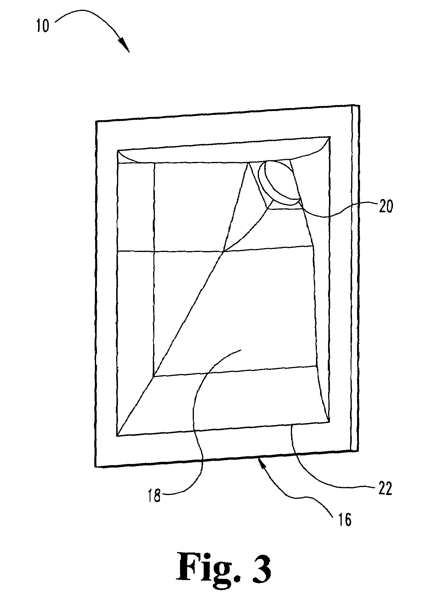
[0035]the present invention is illustrated in FIGS. 3-5 and relates to a flat-front wide dispersion horn or waveguide 10 that may be used alone or as part of an array. Each individual horn 10 may be characterized by at least about 45 degrees and more typically 60 degrees or more of dispersion. Each horn 10 includes a transducer or acoustic source coupling flange 12 for connection to an acoustic source 14, a substantially flat or planar mouth 16 and a flared duct 18 extending therebetween. The coupling flange 12 enables mechanical and acoustic coupling of a transducer 14 thereto via a “bolt on”, “screw on” or like mounting configuration. The application of signal to the transducer 14 results in the transduction of a (typically electrical) signal into modulated air pressure or sound waves. In the case of compression drivers 14, this occurs through oscillation of the voice coil in a magnetic gap. Once produced, the longitudinal sound waves travel down the duct 18, following the steadil...

second embodiment

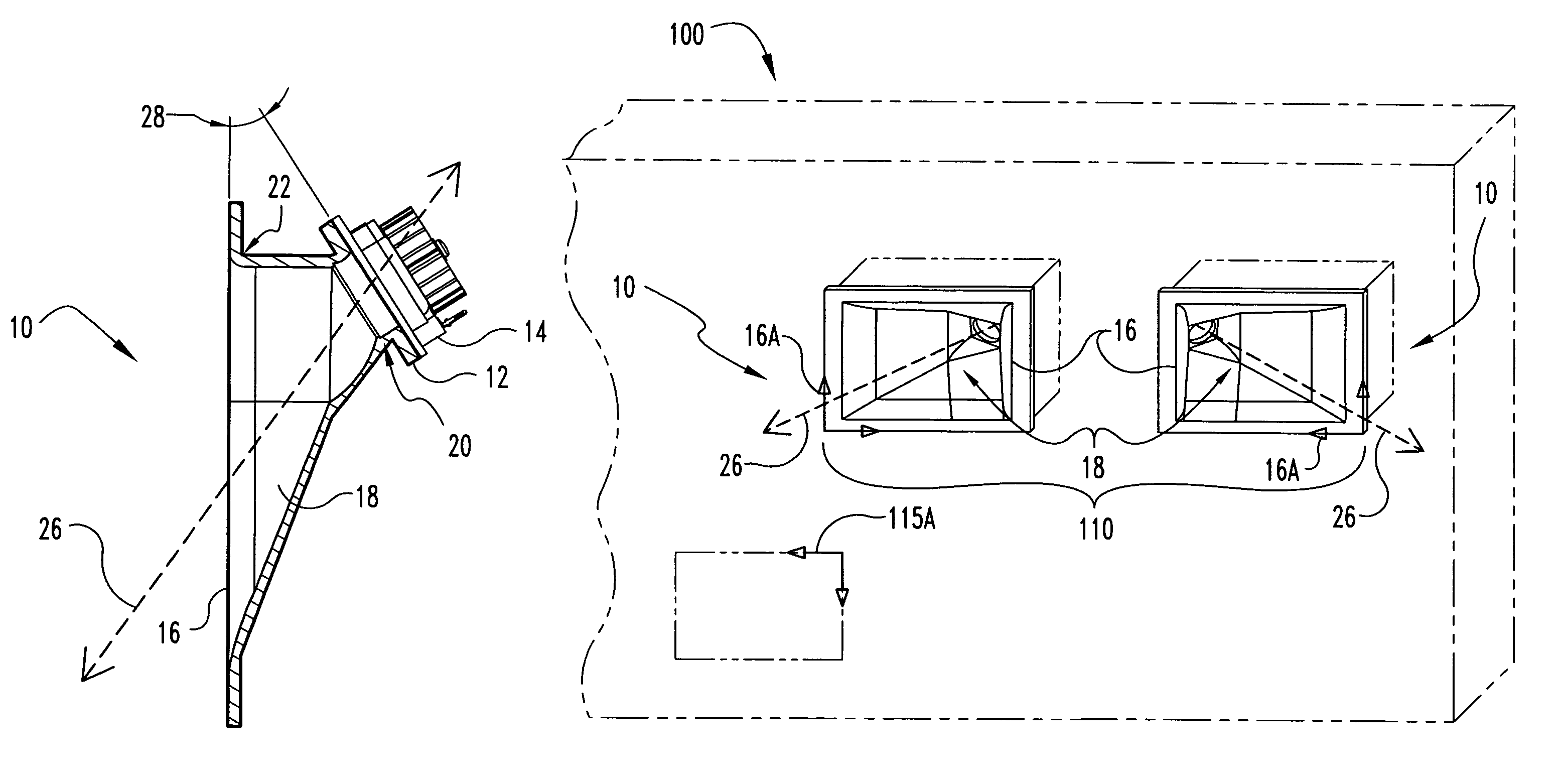
[0039]FIG. 6 illustrates the present invention, a speaker system 100 including a horn assembly 110 having a plurality of horns 10 recessed in a wall. The mouth planes 16A of the horns 10 are coplanar or substantially coplanar with the wall plane 115 defined by the flat surface of the wall. Each horn 10 in the assembly 110 typically defines a mouth 16, an elongated duct 18 and a driver or transducer 14 as described above regarding FIGS. 3-5. The duct 18 is essentially a hollow truncated cone or tube positioned between and acoustically connecting the substantially planar mouth 16 and the driver 14 via the substantially flat coupling flange 12. As above, the driver 14 may typically be thought of as defining a substantially flat output plane 12A coplanar and indistinguishable from the coupling flange plane 12A and nonparallel with the mouth plane 16A. The duct 18 is further characterized by a central or major axis 26 extending therethrough, which is typically normal to the output plane ...


PUM


Abstract

A horn including a substantially flat coupling flange defining a coupling flange plane, a substantially planar mouth defining a mouth plane, an elongated throat extending between the coupling flange and the mouth, a transducer for generating a sonic output operationally connected to the coupling flange, and a major axis extending through the elongated throat. The coupling flange plane and the mouth plane are nonparallel and define a horn angle. The major axis connects the coupling flange and the mouth and the elongated throat is characterized by a substantially steadily increasing sectional area along the major axis from the transducer-connecting end to the mouth connecting end.

Description

TECHNICAL FIELD OF THE INVENTION[0001]The invention relates generally to the field of waveguides, and, more particularly, to a skewed or off-angle horn for a loudspeaker systemBACKGROUND OF THE INVENTION[0002]With the advent of better multi-channel audio technology for movie soundtracks encoded in formats such as DTS, DOLBY DIGITAL®, DVD Audio, DVD-A, Super Audio Compact Disc, SACD, and the like, surround-sound speakers capable of producing wide dispersion output have been in increasingly high demand for both auditorium and home theatre applications. Surround speaker requirements include diffuse dispersion in the horizontal plane to blur the time arrivals to the listener's ear. This concept is referred to as “reverb.” The audio source may be music, a sound effect, or the like. Multiple speakers can be grouped together to provide a wide dispersion of sound, but there is a nontrivial likelihood that the interaction between such acoustic sources will be acoustically destructive, degrad...

Claims


Application Information

Patent Timeline
IPC IPC(8): G10K11/02H04R1/02H04R1/08H04R1/14H04R1/30
CPCG10K11/025H04R1/403H04R2201/403H04R2201/401H04R2201/021
Inventor DELGADO, JR., ROGELIO
Owner KLIPSCH GROUP
Why Eureka
Try Eureka