Calibration wafer and method of calibrating in situ temperatures

a technology of calibration wafers and in situ temperatures, applied in the field of pyrometry calibration systems and methods, can solve the problems of reduced efficiency through lost processing time, difficulty in accurately reading temperature, and reduced accuracy, and achieve the effect of higher reflectivity

Inactive Publication Date: 2007-10-02
VEECO INSTR
View PDF43 Cites 25 Cited by
  • Summary
  • Abstract
  • Description
  • Claims
  • Application Information

AI Technical Summary

Problems solved by technology

Such off-site time or off-line time can result in decreased efficiency through lost processing time.
A problem with these systems as they currently exist is that the pyrometer is attempting to determine temperature readings from surfaces that typically have low emissivity because of their metal contents, making temperature difficult to read accurately.
Accuracy may also be reduced because at the point of melting of the eutectic wafer, other changes in phase, emissivity, and reflectivity may occur that could interfere with accurate temperature measurements and calibration.
In addition, many eutectic wafers require a complex, many-layered design, raising quality control issues and making the wafers more expensive to produce.

Method used


Image

  • Calibration wafer and method of calibrating in situ temperatures
  • Calibration wafer and method of calibrating in situ temperatures
  • Calibration wafer and method of calibrating in situ temperatures

Examples


Embodiment Construction

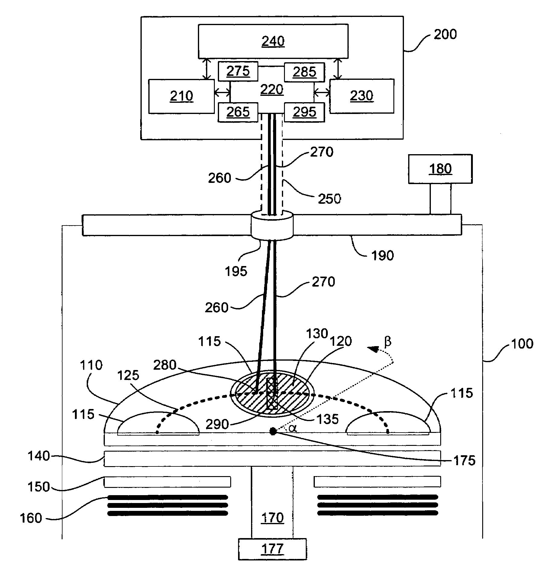
[0024]FIG. 1 shows one embodiment of the pyrometry temperature calibration system of the present invention, as used with a chemical vapor deposition reactor. A chemical vapor deposition reactor (“CVD reactor”) 100 contains a wafer carrier 110 centrally located therein. The wafer carrier 110 includes a plurality of wafer compartments 115. A calibration target wafer 120 is placed in one of the wafer compartments 115 when pyrometer calibration is going to be performed. The other compartments 115 of the wafer carrier typically contain one or more wafer substrates (not shown) on which chemical vapor deposition processes are to be performed.

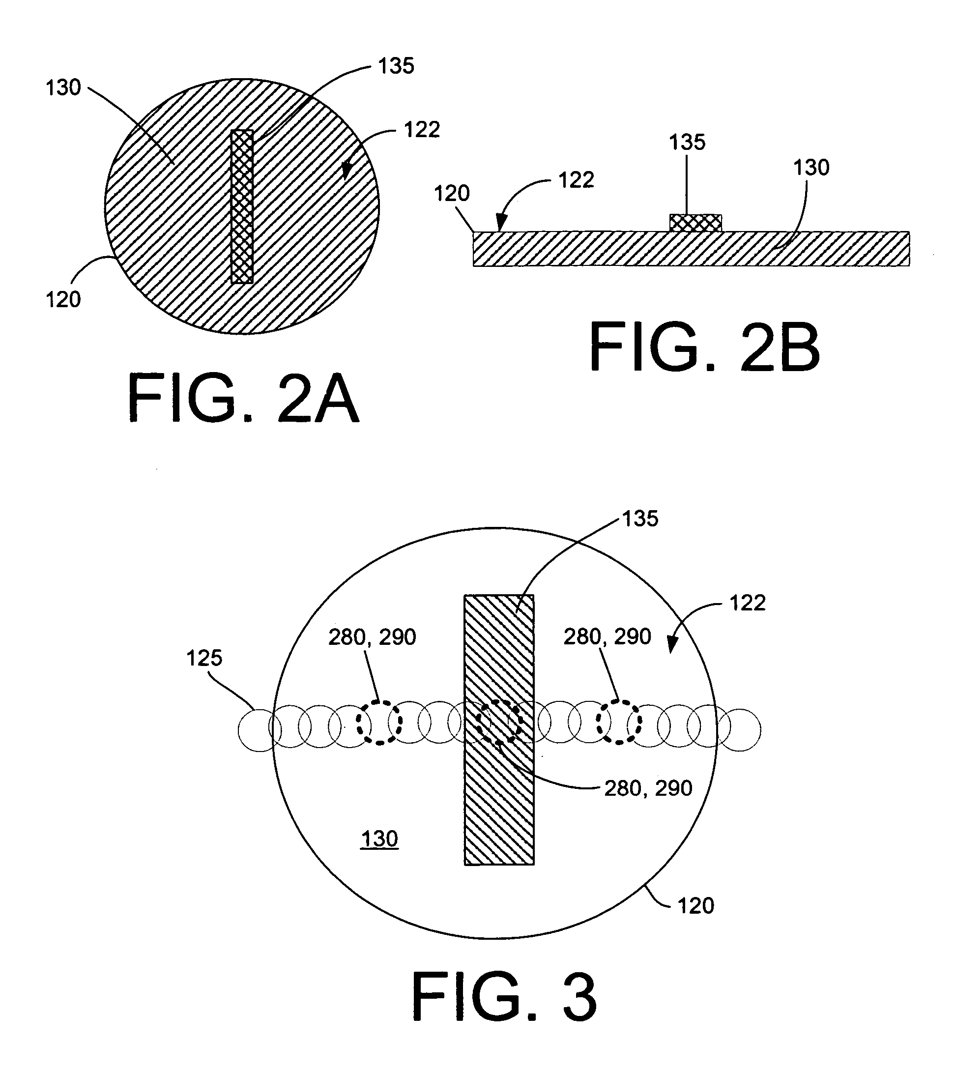
[0025]The calibration target 120 is seated in a wafer compartment 115 that is along optical calibration path 125. The calibration target wafer 120 includes a non-reference region 130 and a reference region 135 described in more detail in FIGS. 2A and 2B, below.

[0026]The wafer carrier 110 is advantageously seated on a susceptor 140 that is itself heated...


PUM

PropertyMeasurementUnit
wavelengthaaaaaaaaaa
wavelength bandaaaaaaaaaa
diameteraaaaaaaaaa

Abstract

A system and method for calibrating a pyrometer used in temperature detection in a chemical vapor deposition system is provided. A calibration wafer with a reference region including a metal such as Al or Ag for forming a eutectic, and an exposed non-reference region without such a metal, are provided. Reflectivity measurements are taken from the reference region, and temperature measurements are taken from the non-reference region, over a range of temperatures including a known melting point for the metal eutectic. The pyrometer is calibrated based on the correlation of the known eutectic melting point with the change in reflectivity data obtained in the reference region, in light of the temperature data obtained from the non-reference region.

Description

BACKGROUND OF THE INVENTION[0001]The present application relates to systems and methods for pyrometry calibration, and more particularly relates to systems and methods for calibrating pyrometers for use in chemical vapor deposition systems using reflectivity and temperature measurements obtained from a eutectic calibration target.[0002]Accurate temperature readings are essential for many industrial processes such as, for example, epitaxial growth of layers on wafers in susceptor-based chemical vapor deposition (“CVD”) systems. Uniform deposition in such systems is dependent on even temperature distribution along with other variables such as, for example, reactor pressure, reactant gas ratios, reactant gas flow rates, and the like. Thus, accurate in situ measurements of CVD reactor temperature are desirable. These temperature measurements preferably should be accurate enough to ensure uniform deposition of layers of material on wafers to be processed.[0003]To measure temperature in C...

Claims


Application Information

Patent Timeline
Patent Type & Authority Patents(United States)
IPC IPC(8): G01K15/00G01J5/00
CPCG01J5/522G01J5/0003G01J5/53
Inventor VOLF, BORISBELOUSOV, MIKHAILGURARY, ALEXANDER
Owner VEECO INSTR
Why Eureka
Try Eureka