
Nested transimpedance amplifier

Inactive Publication Date: 2007-10-02
MARVELL ASIA PTE LTD
View PDF30 Cites 50 Cited by
  • Summary
  • Abstract
  • Description
  • Claims
  • Application Information

AI Technical Summary

Problems solved by technology

However, improving the gain-bandwidth product of TIAs continues to be a challenge for circuit designers.

Method used


Image

  • Nested transimpedance amplifier
  • Nested transimpedance amplifier
  • Nested transimpedance amplifier

Examples


Embodiment Construction

[0044]The following description of the preferred embodiment(s) is merely exemplary in nature and is in no way intended to limit the invention, its application, or uses.

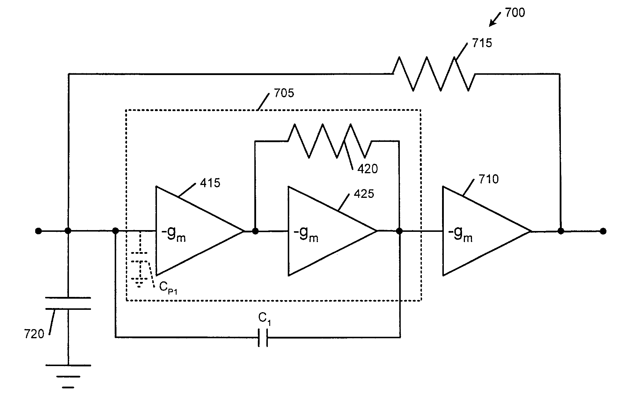
[0045]The present invention addresses the need for increasing the gain-bandwidth product of TIAs. Improvements in the gain-bandwidth product are achievable by “nesting” a TIA within another TIA. In other words, additional circuit elements such as feedback resistors, capacitors and / or opamps are added on the input and / or output sides of the TIA. In FIGS. 15–17, capacitive cancellation of the input parasitic capacitance is provided. In FIGS. 20–24, additional feedback resistance is provided. In FIGS. 23 and 24, input and / or feedback capacitance is provided.

[0046]Referring now to FIGS. 7, 8, and 9, a “nested” TIA is constructed by adding opamps, feedback resistors and / or capacitors to a zero-order TIA. In FIGS. 10 and 11, a nested TIA may also be constructed to operate in a differential mode.

[0047]Referring back to FIG. ...


PUM


Abstract

A nested transimpedance amplifier (TIA) circuit includes a zero-order TIA having an input and an output. A first operational amplifier (opamp) has an input that communicates with the output of the zero-order TIA and an output. A first feedback resistance has one end that communicates with the input of the zero-order TIA and an opposite end that communicates with the output of the first opamp. A first feedback capacitance has a first end that communicates with the input of the zero-order TIA and a second end that communicates with the output of the zero-order TIA. A capacitor has one end that communicates with the input of the zero-order TIA.

Description

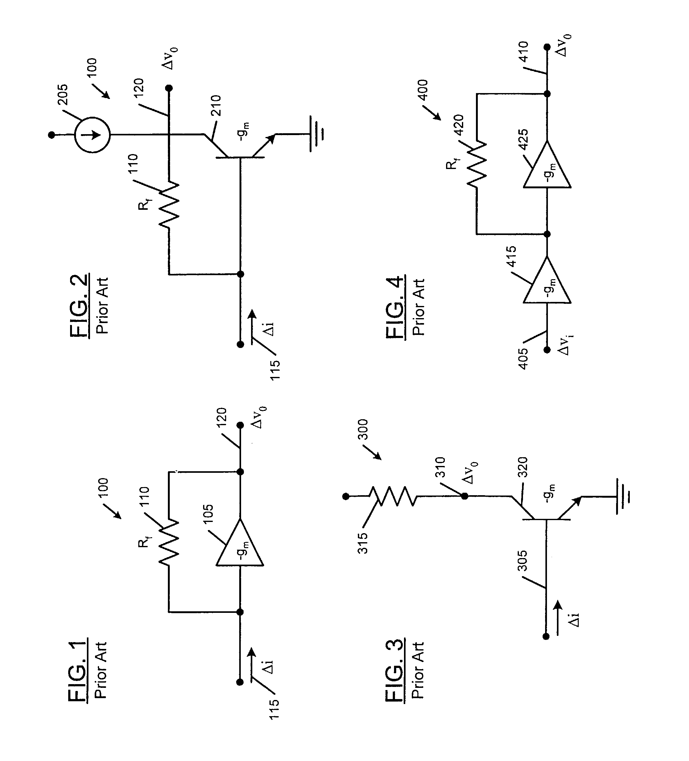
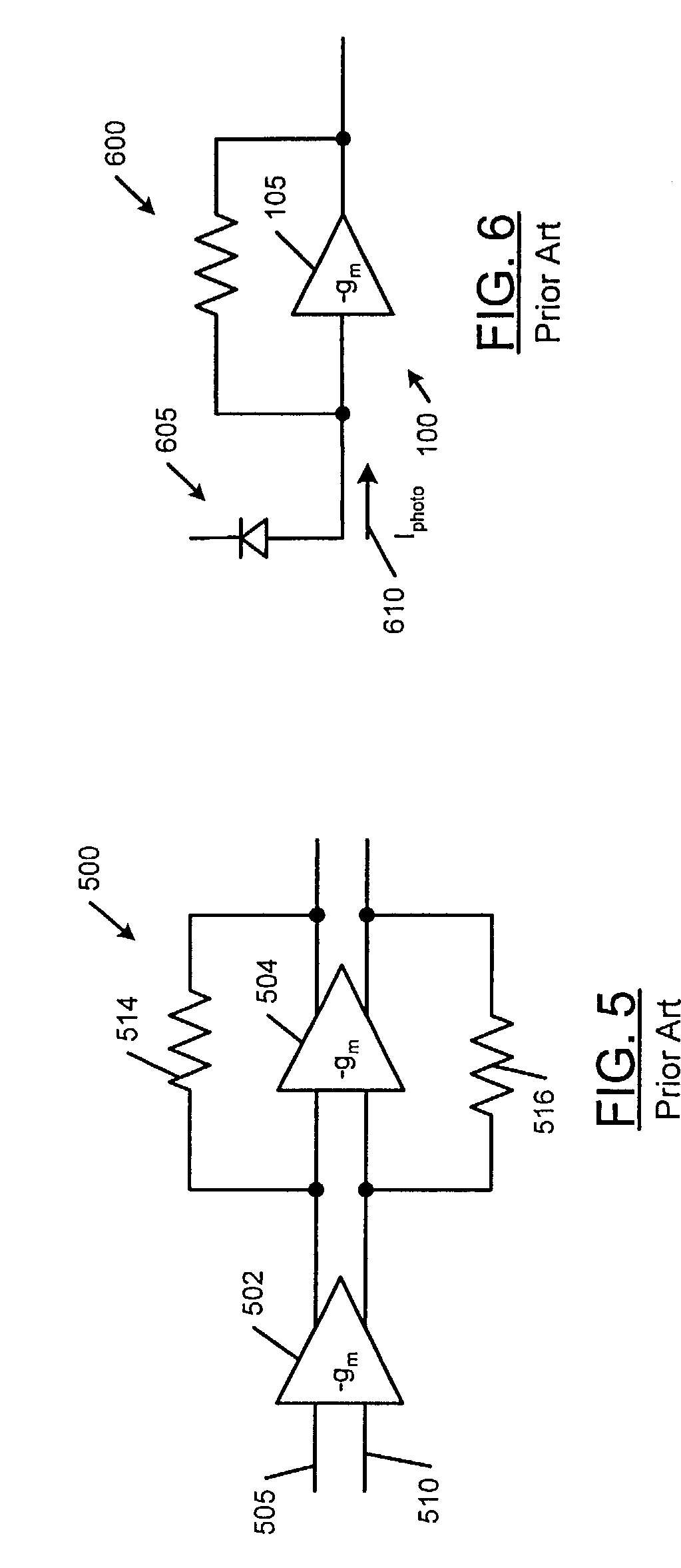
CROSS-REFERENCE TO RELATED APPLICATIONS[0001]This application is a continuation-in-part of U.S. patent application Ser. No. 10 / 072,843 filed on Feb. 6, 2002 now U.S. Pat. No. 6,762,644, which claims the benefit of U.S. Provisional Application No. 60 / 275,109, filed Mar. 13, 2001, both of which are hereby incorporated by reference in their entirety.FIELD OF THE INVENTION[0002]The present invention relates to transimpedance amplifiers, and more particularly to nested transimpedance amplifiers with an increased gain-bandwidth product.BACKGROUND OF THE INVENTION[0003]A transimpedance amplifier (TIA) is a well-known type of electronic circuit. Referring now to FIG. 1, a TIA 100 includes an operational amplifier (opamp) 105 having a gain parameter (−gm). The opamp 105 is connected in parallel to a resistor (Rf) 110. The input to the TIA 100 is a current (Δi) 115. The output of the TIA 100 is a voltage (Δvo) 120.[0004]Referring now to FIG. 2, the opamp 105 of the TIA 100 is replaced by a cu...

Claims


Application Information

Patent Timeline
Patent Type & Authority Patents(United States)
IPC IPC(8): H03F1/24
CPCH03F1/08H03F1/486H03F3/19H03F1/34H03F3/45071H03F2200/405H03F2200/36H03F2203/45528
Inventor SUTARDJA, SEHAT
Owner MARVELL ASIA PTE LTD
Learn More