Boundary representation per feature methods and systems

a feature and feature technology, applied in the field of data exchange methodologies for computer aided design systems, can solve problems such as inability to support collaborative editing, inability to design work, and different modeled cad file systems

Inactive Publication Date: 2007-10-02
PROFICIENCY
View PDF11 Cites 21 Cited by
  • Summary
  • Abstract
  • Description
  • Claims
  • Application Information

AI Technical Summary

Problems solved by technology

In particular, a significant technical problem for such people is not always the design work they do, but rather the means by which their design work is shared and exchanged with other engineers, scientists, designers, manufacture

Method used


Image

  • Boundary representation per feature methods and systems
  • Boundary representation per feature methods and systems
  • Boundary representation per feature methods and systems

Examples


Embodiment Construction

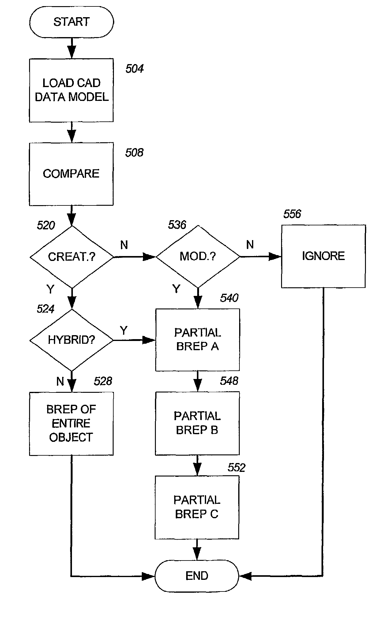
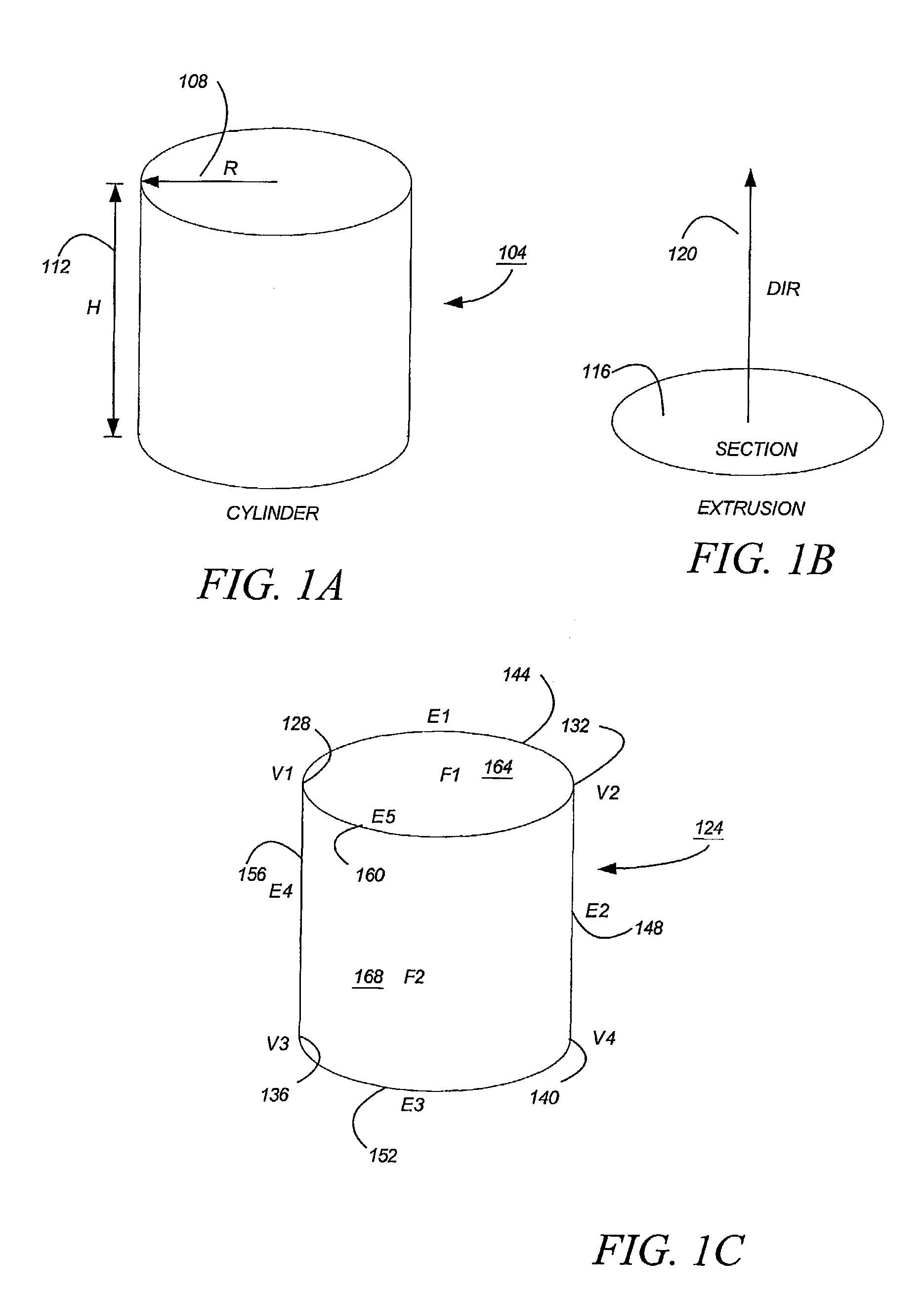
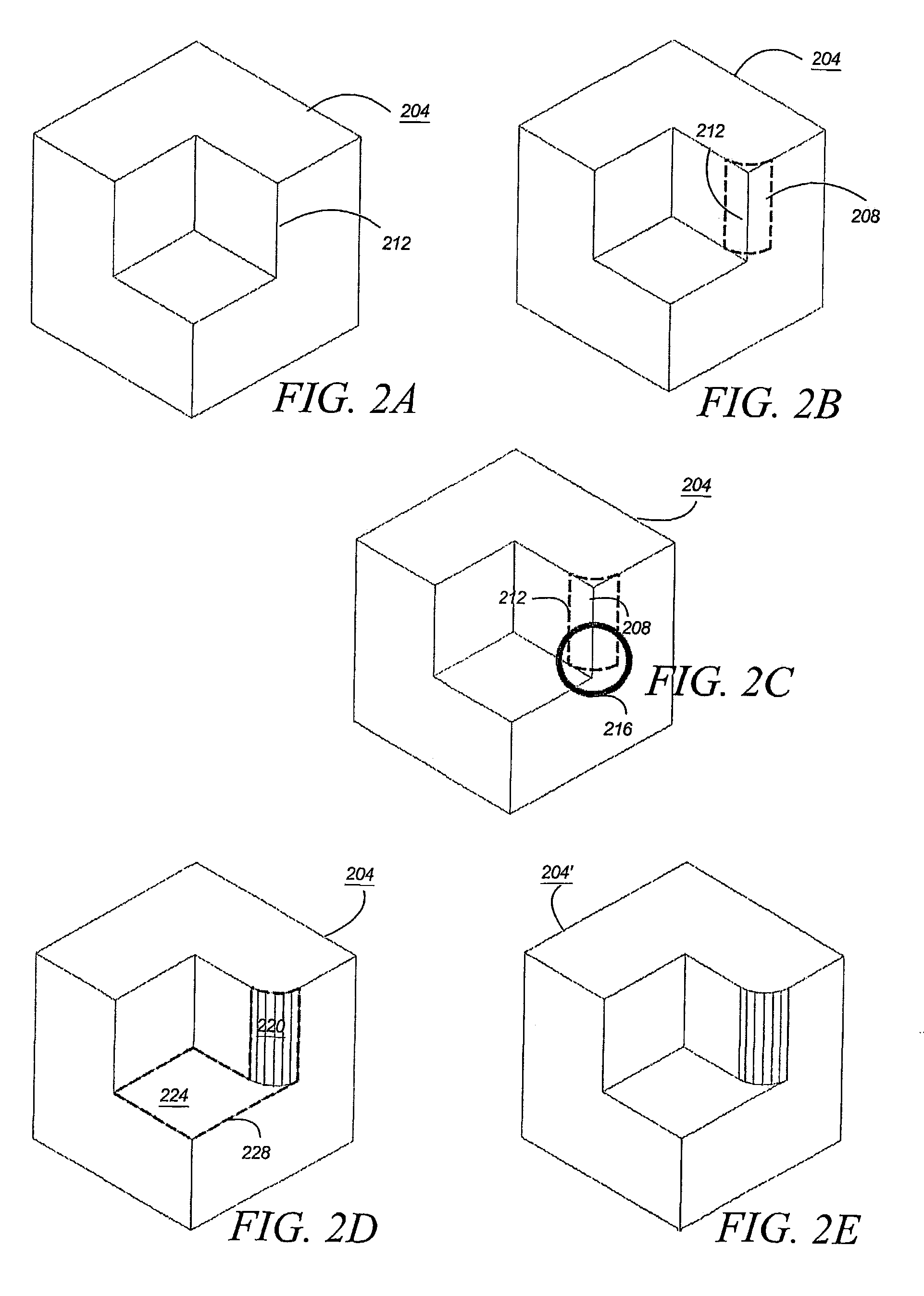
[0028]When a geometric object is constructed in a CAD system, and more particularly a PFBD system, the solid is typically specified as a sequence of operations, which are called features. Each of these operations creates new geometry or modifies an existing geometry. The result of the geometries, all of them together, is sometimes called a boundary representation, or “brep”. Hence, in ordinary usage, a brep is not a feature, but the overall geometry of the object—the geometric point sets of the object which allow the object to be rendered in a CAD system. Departing from common usage of the term, brep in this detailed description is inclusive of a brep of a feature.

[0029]In U.S. patent application Ser. No. 09 / 655,540 and published PCT International Application No. PCT / US00 / 01357, both filed Sep. 6, 2000, and entitled “DATA EXCHANGE BETWEEN COMPUTER AIDED DESIGN SYSTEMS”, both of which are incorporated herein by reference in their entirety where permissible under applicable patent law...


PUM


Abstract

Computer implemented methods and systems for CAD data exchange, and in particular for creating boundary representations (“breps”) on a feature-by-feature basis are disclosed. According to an embodiment of the techniques described herein, a parameterized feature from a parametric based design system is exported from a source CAD system (404). Iterative steps and complimentary extraction techniques are employed by one or more processors (452, 456) to create an importable design model of the parameterized feature (433), which is imported into a target CAD system (408). While the techniques can include API (436), pattern matching (440), and user emulation (444) techniques, they include a brep per feature (450) technique. By exporting the brep on a per feature (453) basis from the source CAD system (404), the design intent of a CAD designer can be preserved on importation into the target CAD system (408). In particular, where a parametric representation (433) of the feature fails to import into the target system (408), an unparameterized representation (453) of the feature can be substituted.

Description

CROSS-REFERENCE TO RELATED APPLICATIONS[0001]This application is related to U.S. Provisional Application Ser. No. 60 / 297,014, filed on 8 Jun. 2001 and having the same title. Priority is claimed to the '014 application. This application is also related to U.S. patent application Ser. No. 09 / 655,540, filed on Sep. 6, 2000, entitled “DATA EXCHANGE BETWEEN COMPUTER AIDED DESIGN SYSTEMS,” also to which priority is claimed, and published PCT International Application No. PCT / IS00 / 01357, both filed on Sep. 6, 2000, also entitled “DATA EXCHANGE BETWEEN COMPUTER AIDED DESIGN SYSTEMS,” to which priority is also claimed. All three applications are incorporated herein by reference in their entirety.BACKGROUND[0002]1. Field of the Invention[0003]This application concerns data exchange methodologies for computer aided design systems, and in particular boundary representation techniques.[0004]2. Background Information[0005]In an earlier filed patent application, we discussed some of the challenges...

Claims


Application Information

Patent Timeline
IPC IPC(8): G06G7/56G06F17/10G06F17/50G06T15/00G06T17/20G09G1/14G06F9/455G06TG06T17/00
CPCG06T17/10
Inventor SPITZ, STEVENRAPPOPORT, ARI
Owner PROFICIENCY
Why Eureka
Try Eureka