
Array and method for tying cable trees and the like and method for the production of strips

a technology of tying cable trees and tying wires, which is applied in the direction of hose connections, flexible container closures, other domestic objects, etc., can solve the problems of repeated stress and possibly damage, damage to the teeth of the lock, and damage to the other side, so as to increase the reliability

Inactive Publication Date: 2007-10-09
HELLERMANN TYTON GMBH
View PDF8 Cites 4 Cited by
  • Summary
  • Abstract
  • Description
  • Claims
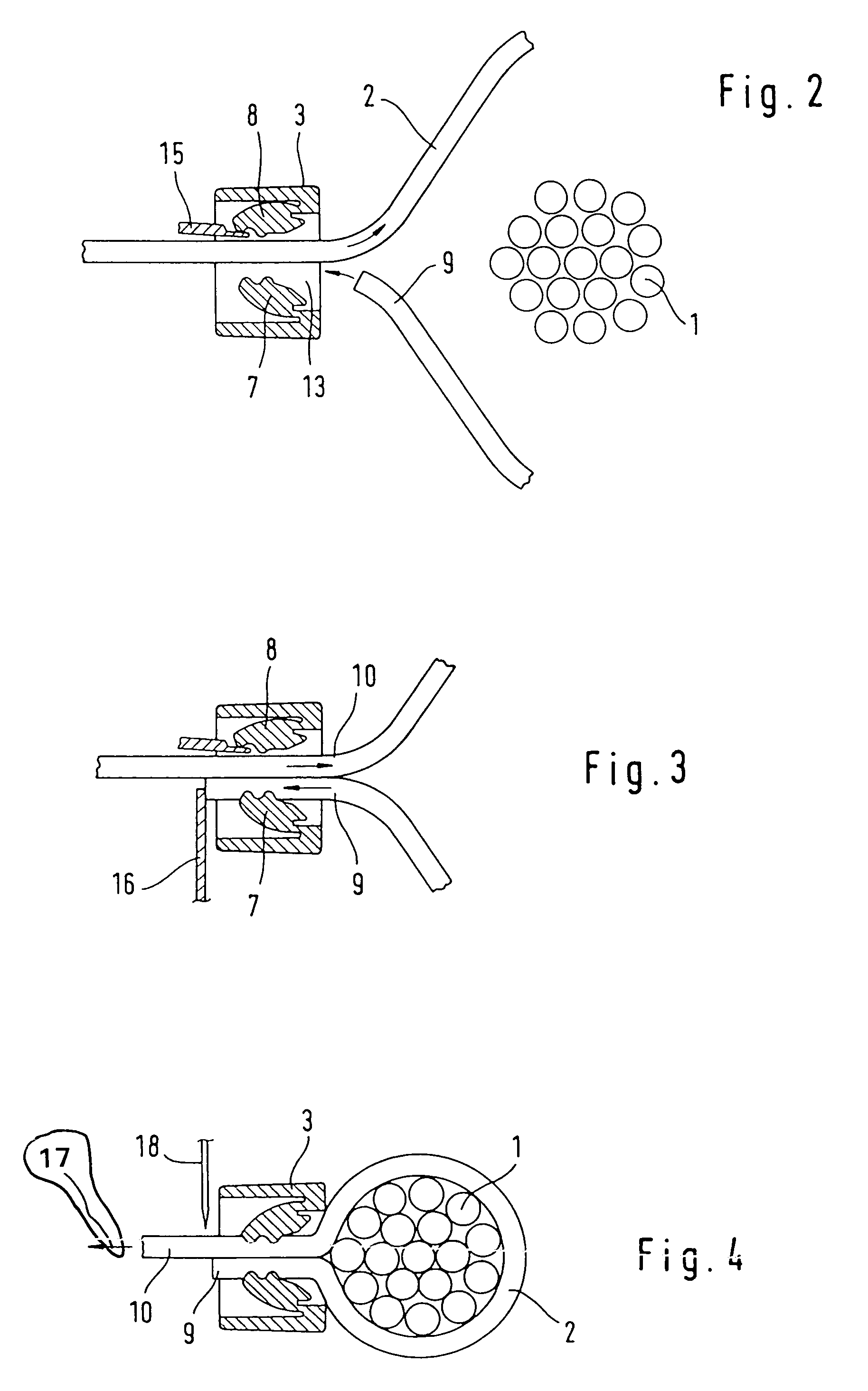
  • Application Information

AI Technical Summary

Benefits of technology

[0005]It is an object of the invention to reduce the required safety margin or clearance required between the teeth of the lock and the teeth of the strip during installation of the strip.
[0006]It is also an object of the invention to avoid the reduction in blocking force brought about as a result of rounding the teeth.
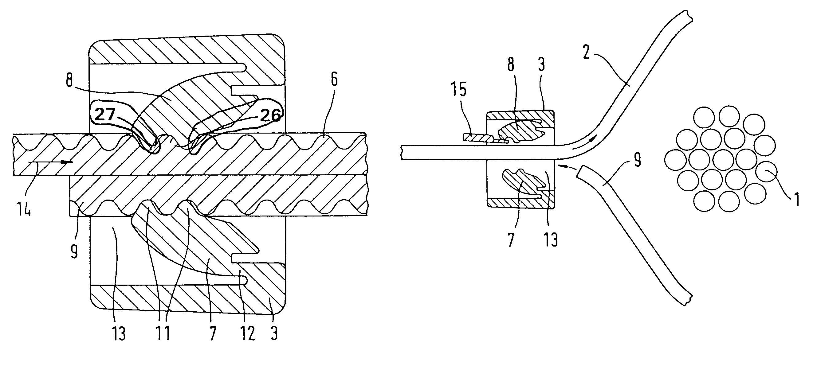
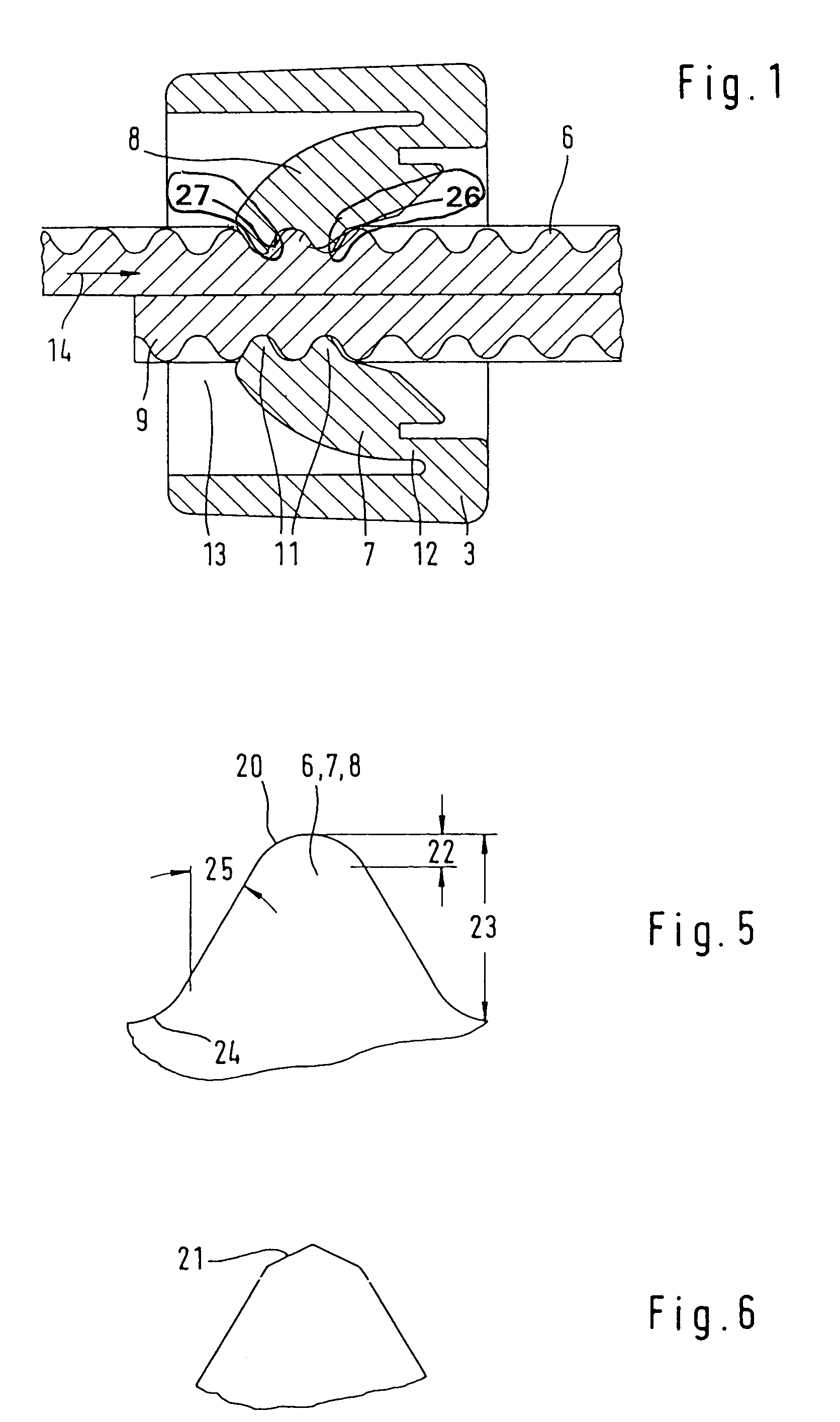
[0007]Accordingly, the teeth tips of the blocking device and the teeth bases of the strip are rounded off or beveled at least on their sides lying against one another in the tightened state. This achieves the effect that the teeth tips both of the strip and of the lock are damaged less easily. Furthermore, it achieves the effect that the safety margin which has to be maintained when the strip is pushed forward between the teeth of the strip and the blocking teeth can be reduced. This is so because it is not absolutely necessary for contact to be avoided if the teeth slide past one another more easily thanks to the rounding. This applies in particular whenever, according to a further feature of the invention, the tips of the teeth on the strip are also rounded off or beveled. In this case, the bases of the teeth on the blocking device are also rounded off or beveled. The rounding-off or beveling expediently relates to both sides of the teeth tips and teeth bases of the strip, in particular symmetrically.
[0008]The rounding-off of the tips of the teeth on the blocking device has the consequence that the force transfer between the blocking device of the lock and the teeth of the strip does not take place directly at the transition from the teeth of the strip to the continuous strand cross section, but at a certain distance from it. Contrary to previous opinion, however, this does not constitute a disadvantage. On the contrary, the rounding-off of the tooth base avoids the teeth of the strip being over stressed by a notch effect at this point. This applies in particular if the tooth profile of the strip is produced by embossing a strand of hot-plastic polymer. This is so because particularly strong flowing of the strip material then takes place in the region of the surface of the tooth base, whereby the elongate molecules or the reinforcing fibers possibly contained in the material are structured parallel to the surface of the tooth base. As a result, a significant increase in strength with respect to the forces occurring at this point is achieved.
[0009]Furthermore, it has been found that the stressing of the teeth when they slide through the lock leads less readily to damage, and that the risk of the teeth deforming under the blocking force also occurs less readily if the flank angle of the teeth (i.e. the angle between a flank and a line taken perpendicular to the direction of the strip) is chosen to be relatively large, that is over 25 degrees. Furthermore, it may be expedient to restrict the rounding-off or beveling to no more than approximately one quarter of the overall height of the teeth of the strip, it expediently extending over no more than 0.1 mm (measured in the direction of the strip height). It is, however, also normally intended to take up not less than one eighth of the tooth height.
[0010]The arrangement described has proven successful in particular in those tying methods in which the strip is initially passed through the lock in a pushing-forward direction counter to the blocking devices, the free end of the loop formed thereby is wrapped around the item, led back into the lock and the other end of the loop, which is joined to the supply of strip, is led back counter to the pushing-forward direction. In the case of such an arrangement, the end joined to the supply of strip has to move counter to the blocking devices assigned to it not only when the free end of the strip is located outside the lock and is moving around the item to be tied but also when the free end of the strip is being led back into the lock, and therefore the space in the lock between the mutually opposite blocking devices is confined. Although the blocking device directed counter to the pushing forward of the strip is still forcibly kept away from the teeth of the strip in this phase, if the rounding-off or beveling of the teeth tips according to the invention has the effect that the movement is not stopped when there is inadvertently slight contact of the teeth with the blocking devices, no great safety margin need be maintained between the teeth of the strip and the blocking devices. The lock can correspondingly be given smaller dimensions. This increases the reliability and reduces the necessary dimensions of the lock, and consequently also the material requirement.

Problems solved by technology

As this happens, its teeth slide along the teeth of the other blocking device, which may cause them to damage one another.
If items of a very small circumference are to be tied, it may happen that several teeth of the strip run past the teeth of the locks during a number of successive tightening operations and, as a result, are repeatedly stressed and possibly damaged before they are finally themselves used for the blocking function in a later tying operation.
The teeth of the lock may also be damaged in the process.
This is that it is endeavored to make the engagement of the teeth of the blocking device into the teeth of the strip take place as close as possible to the tooth base, that is to say at the connection of the tooth to the continuous strand cross section of the strip, because otherwise there is the risk of the tooth of the strip bending and the tooth of the lock sliding off it.

Method used


Image

  • Array and method for tying cable trees and the like and method for the production of strips
  • Array and method for tying cable trees and the like and method for the production of strips
  • Array and method for tying cable trees and the like and method for the production of strips

Examples


Embodiment Construction

[0015]An item, for example a bundle of cables 1, is to be tied by means of the strip 2 and lock 3 in the way shown in FIG. 4 (shortly before completion of the tying operation). For this purpose, a tool of the type shown in EP-A-297 337 is used. The strip 2 has teeth 6 on one side. The lock 3 contains blocking devices, which are formed by a first blocking pawl 7, which acts together with the free end 9 of the strip 2, and a second blocking pawl 8, which acts together with the end 10 of the strip 2, on which the pushing-forward members within a tying device act and which is joined to a supply of strip (not shown). For this purpose, the blocking pawls 7, 8 have teeth 11, the shape of which is made to match that of the teeth 6 of the strip. They protrude obliquely from a point of articulation 12 into the opening 13 located in the lock in such a way that they hinder the strip end 9, 10 respectively acting together with them from moving in the direction of the arrow 14. Although the teeth...


PUM

PropertyMeasurementUnit
Angleaaaaaaaaaa
Massaaaaaaaaaa
Heightaaaaaaaaaa

Abstract

Tying arrangement comprising a strip, which is serrated at least on one side, and a lock, which is intended for receiving two ends of a portion of the strip and contains at least one blocking device, which is serrated in such a way as to match the serration of the strip. In order to preserve the tips of the teeth, the teeth tips of the teeth provided on the blocking device and the teeth bases of the strip are rounded off or beveled at least on their sides lying against one another in the tightened state. Such an arrangement is used in tying methods in which the free strip end is led back into the lock after wrapping around the item to be tied.

Description

CROSS-REFERENCE TO RELATED APPLICATIONS[0001]This is the national stage of International Application No. PCT / EP02 / 01239, filed Feb. 6, 2002 and which designated the United States.BACKGROUND OF THE INVENTION[0002]Strips for tying cable harnesses and other items are known, said strips being used in the form of portions of a long supply of strip. Both ends of a strip loop wrapped around the item to be tied and tightened are secured by means of a lock. Provided within the lock are two serrated blocking devices, which act together in a blocking manner with a serration of a respective end of the strip loop (U.S. Pat. No. 4,680,834, GB-A 2055218, EP-A-488 051, EP-B-297 337).[0003]At the beginning of the tying operation by means of a tool, a portion of the strip is pushed forward through a lock, its teeth being kept away from the oppositely directed teeth of the blocking devices. The strip is passed around the item in the form of a loop, the length of which is greater than the circumference...

Claims


Application Information

Patent Timeline
IPC IPC(8): B65D63/14F16B2/08F16L3/233H02G3/30
CPCB65D63/14F16L3/2336Y10T24/153Y10T24/1498
Inventor KURMIS, VIKTOR
Owner HELLERMANN TYTON GMBH
Learn More