Pressure sensor and method for fabricating the same

a technology of pressure sensor and manufacturing method, applied in the field of pressure sensor, can solve the problems of weakened force and loss of flexibility

Inactive Publication Date: 2007-10-09
SANYO ELECTRIC CO LTD +1
View PDF8 Cites 19 Cited by
  • Summary
  • Abstract
  • Description
  • Claims
  • Application Information

AI Technical Summary

Benefits of technology

[0007]The present invention has been made in light of the above problems, and it is an object of the present invention to provide a pressure sensor having a sensor section with fewer failures and proper sensitivity.

Problems solved by technology

If a film thickness is reduced in order to obtain a flexibility, however, a restoring force is weakened, while if a film thickness is increased in order to enhance a restoring force, a flexibility is lost; therefore, it has been difficult to achieve the second meal layer 105 having sufficient flexibility and sufficient restoring force in a conventional technology.

Method used


Image

  • Pressure sensor and method for fabricating the same
  • Pressure sensor and method for fabricating the same
  • Pressure sensor and method for fabricating the same

Examples


first embodiment

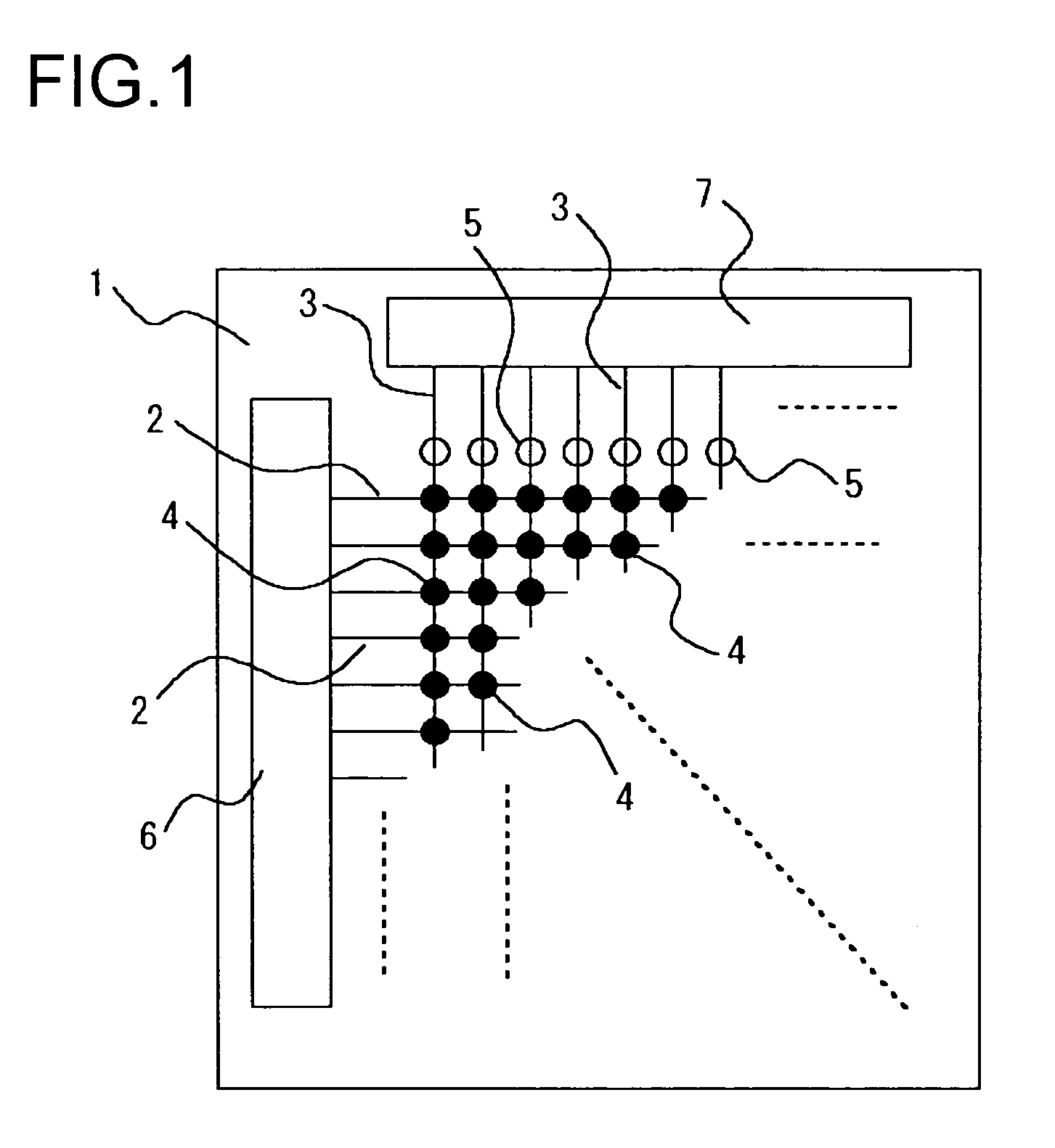
[0043]At first, description will be given of a first embodiment with reference to the accompanying drawings. FIG. 1 is an overall view schematically showing pressure sensors of the present invention. A numerical symbol 1 indicates a transparent glass substrate, and intersections between plural first wires 2 extending in the row direction and plural second wires 3 extending in the column direction are arranged in a matrix on the glass substrate 1. In this embodiment, while the glass substrate 1 is used as a substrate, a plastic film or the like may also replace it without imposing specific limitation on the glass substrate. A numerical symbol 4 indicates sensor sections each disposed in the vicinity of intersections of the first wires 2 and the second wires 3, and a numerical symbols 5 indicates vent hole sections provided on the respective second wires 3. A region in which the plural sensor sections 4 are arranged in a matrix corresponds to a pressure detection region, which detects...

fourth embodiment

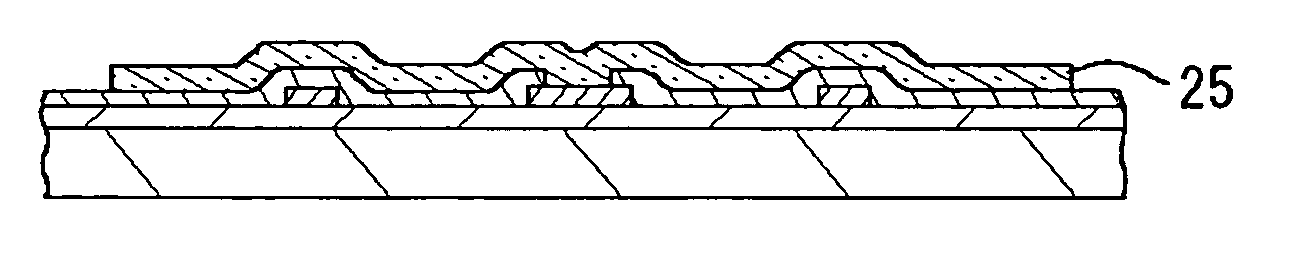
[0094]A numerical symbol 29 indicates an overcoat film, and the overcoat film 29 covers the second electrode 9. A numerical symbol 16 indicates a second insulating film and a numerical symbol 17 indicates a protective film, and the second insulating film 16 and the protective film 17 are stacked on the overcoat film 29. The overcoat film 29, the second insulating film 16 and the protective film 17 are the same as those in the fourth embodiment in material and construction; therefore, description thereof will not be repeated herein.

[0095]Since while the second electrode 9 itself is at an almost uniform thickness, a surface profile of the intermediate layer 25 assumes a profile of depression and protrusion combined in conformity with that of the first insulating film 13; therefore, the second electrode 9 also assumes a wavy profile. That is, the second electrode 8 rises at site where the first insulating film 13 exists, while sinking at a site of the recess 28, wherein if the rise and...

fifth embodiment

[0115]While in this embodiment, description is given of the case where the end edge of the first insulating film 13 is located at the peripheral portion of the first electrode 8, the present invention is also effective for a case where part of the first insulating film 13 exists in the central portion of the first electrode 8. For example, in the case of the fifth embodiment, as well, the end edge of the first insulating film 13 is preferably inclined.

[0116]In the embodiments, all of the insulating film on the second electrode is removed or only the thin overcoat film is left thereon. With such a construction, the optimal flexibility and the optimal restoring force can be imparted to the second electrode, while another film may be stacked on the second electrode 9 in a manner such that the restoring force and the flexibility are not lost. For example, an insulating film with a thickness may be provided in the central portion of a sensor section or a different insulating film may be ...


PUM

PropertyMeasurementUnit
thicknessaaaaaaaaaa
diameteraaaaaaaaaa
diameteraaaaaaaaaa

Abstract

A pressure sensor comprising a plurality of sensor parts arranged in matrix. A first electrode being connected with first wiring and a second electrode being connected with second wiring are disposed oppositely through a cavity part in the sensor part. The second electrode bends to the first electrode side in response to a pressure from a specimen and touches the first electrode upon application of a pressure of a specified level or above. When the specimen is pressed against a pressure detecting region, both electrodes touch each other at a sensor part corresponding to a protrusions of the specimen and are separated at a sensor part corresponding to a recess. When a scanning signal is fed from a scanning circuit to one wiring and presence of a signal flowing through the second wiring is detected by a sensing circuit, a pressure being applied to each sensor part can be detected. Furthermore, the shape is detected by feeding the scanning signal from the scanning circuit to each first wiring sequentially and scanning the pressure detecting region generally.

Description

CROSS-REFERENCE TO RELATED APPLICATION[0001]This application is a National Stage entry of International Application No. PCT / JP03 / 03898, filed Mar. 27, 2003, the entire specification claims and drawings of which are incorporated herewith by reference.TECHNICAL FIELD[0002]The present invention relates to a pressure sensor and, more particularly, to a sensor for detecting a fine pattern.BACKGROUND ART[0003]A finger print sensor has been conventionally employed as an individual identification device, and a requirement for the finger print sensor is detection of a finger print with simplicity and good precision. Various types of finger print sensors of this kind have been studied and developed, which include a type to detect a finger print optically, a type to detect a finger print electrically, and the like. JP-A 09-126918 (1997) and JP-A 10-300610 (1998) describe, for example, that microsensor sections having electrodes are arranged in a matrix, wherein a pressure from a finger is conv...

Claims


Application Information

Patent Timeline
Patent Type & Authority Patents(United States)
IPC IPC(8): G01L9/00B81B3/00G01L1/14G01L1/20G01L5/22G06K9/00
CPCG01L1/14G06K9/0002G01L5/228G01L1/205G06V40/1306G01L5/00G01L1/20
Inventor KOBAYASHI, CHIAKISUMI, DAISUKEINAMURA, HIROSHIMORIFUJI, TOGOYOSHIDA, KOJIENDO, MASAKIHIURA, SAYAKAYAMAUCHI, TAKAOYAMAURA, SYUNSUKETAKETA, KAORUNAGAMI, KIMIHIKO
Owner SANYO ELECTRIC CO LTD
Why Eureka
Try Eureka