Cooling structure of cylinder block
a technology of cylinder block and cooling structure, which is applied in the direction of cylinders, engine cooling apparatus, liquid cooling, etc., can solve the problems of insufficient cooling of the boundary between the bore regions adjacent to each other, and insufficient cooling of the temperature of the bore wall
- Summary
- Abstract
- Description
- Claims
- Application Information
AI Technical Summary
Benefits of technology
Problems solved by technology
Method used
Image
Examples
first embodiment
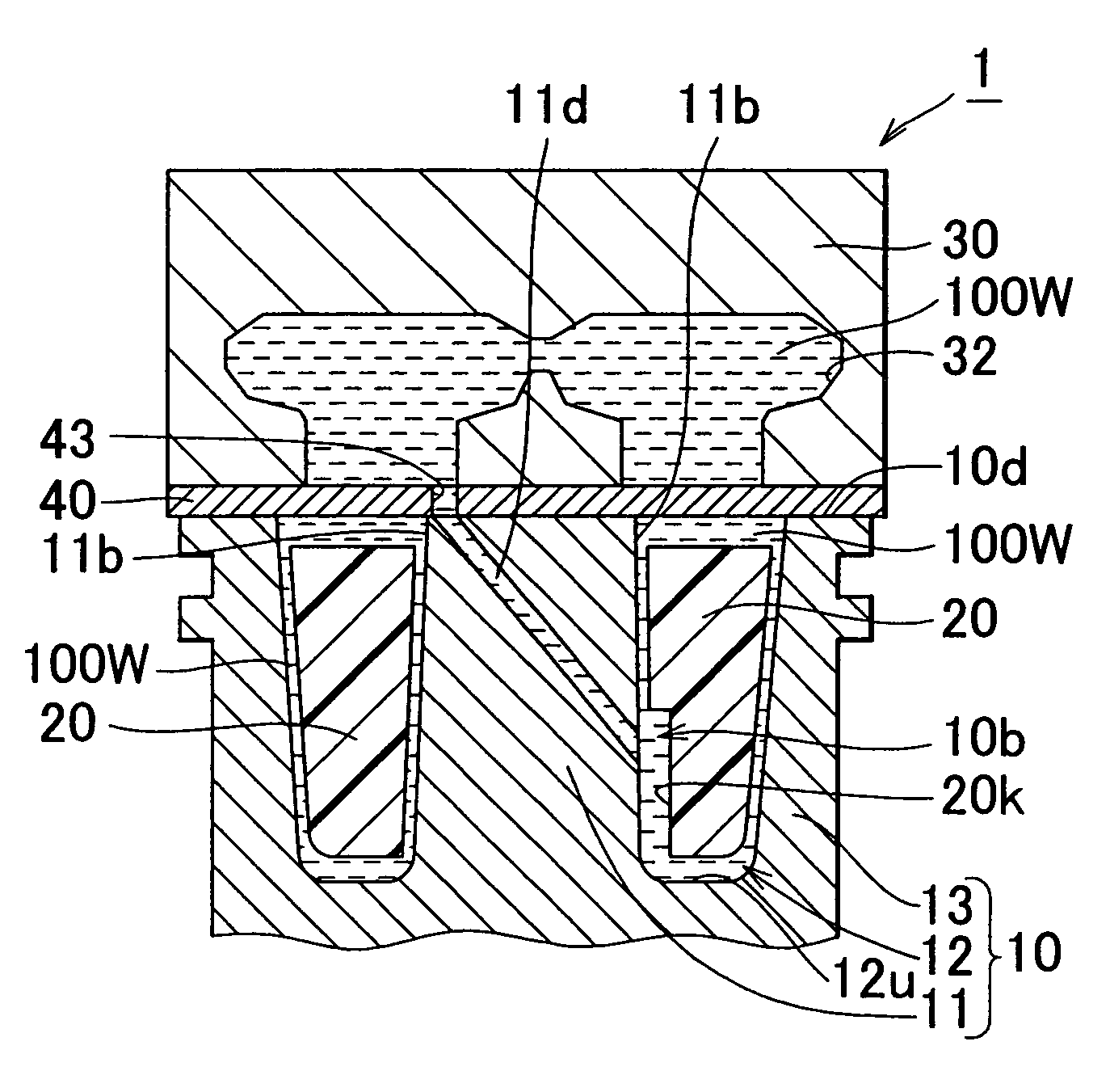
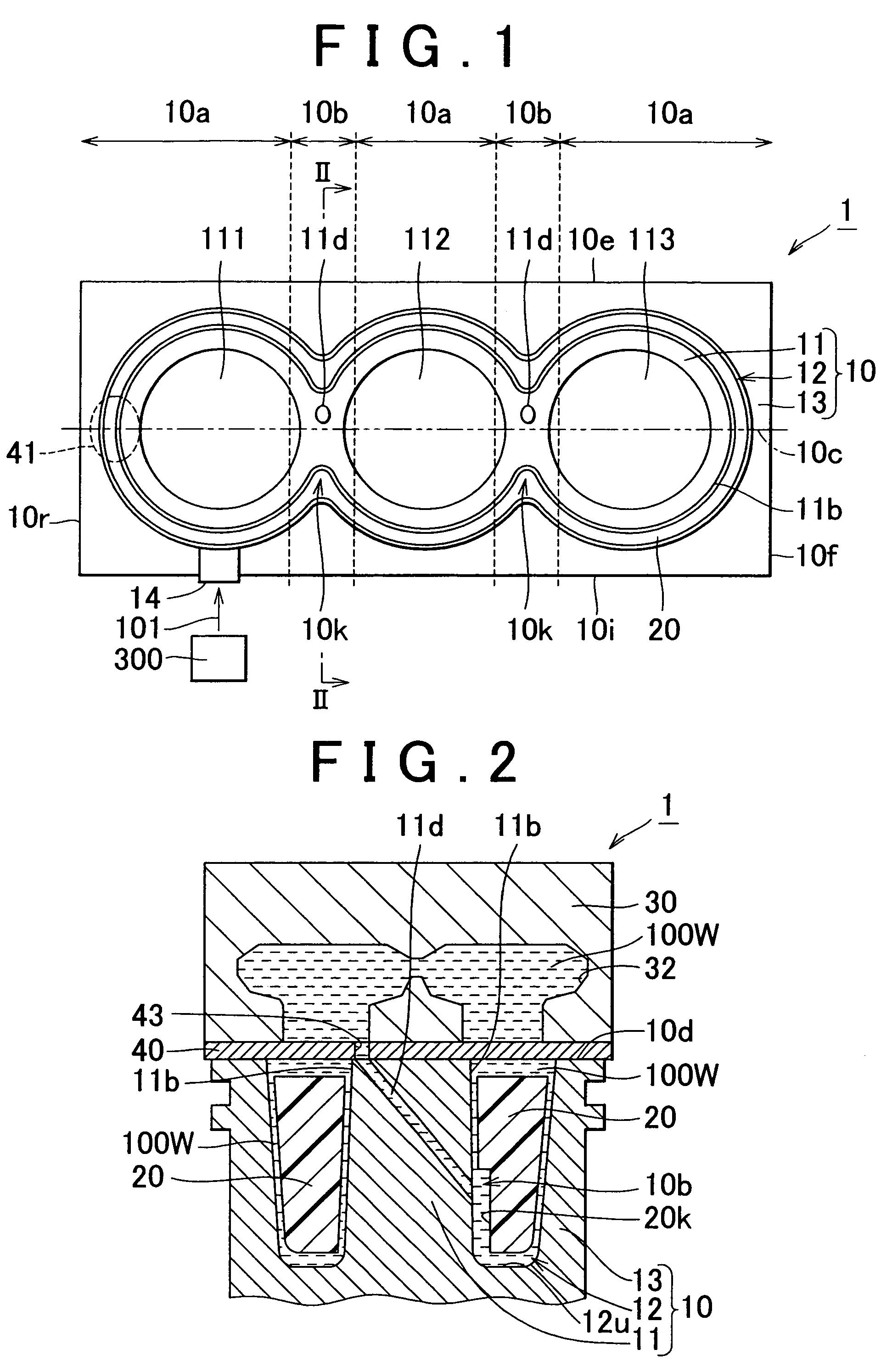
[0041]FIG. 2 is a cross sectional view taken along line II—II in FIG. 1. As shown in FIG. 2, in the cooling structure 1 of a cylinder block according to the invention, the cylinder block 10 includes the cylinder liner assembly 11 which is provided inside the cylinder block 10; the water jacket portion 12 which is provided so as to surround the cylinder liner assembly 11, and which serves as the cooling medium passage; and the cylinder block base portion 13 which surrounds the water jacket portion 12, and which is opposed to the cylinder liner assembly 11.
[0042]The cylinder liner assembly 11 includes the bore wall 11b, and the bore wall 11b contacts coolant 100W that is the cooling medium.
[0043]The water jacket portion 12 is a region provided between the cylinder liner assembly 11 and the cylinder block base portion 13. The water jacket portion 12 serves as the passage for the cooling medium. The water jacket portion 12 includes a bottom portion 12u. The cylinder liner assembly 11 is...
second embodiment
[0057]That is, in the invention, the passage is the drill path 11d, and the flow promotion means is the penetrating hole which is formed in the water jacket spacer 20 in the vicinity of the opening of the drill path 11d. Since the penetrating hole 20h is provided, it is possible to promote the inflow of the coolant at the inlet of the drill path 11d, that is, at the opening of the drill path 11d which is provided in the bore wall 11b. When the coolant 100W flows into the drill path 11d from the water jacket portion 12, pressure of the coolant in the vicinity of the opening is reduced. However, since the penetrating hole 20h is provided as shown in FIG. 6, it is possible to actively supply the coolant 100W to the drill path 11d from the region between the water jacket spacer 20 and the cylinder block base portion 13.
[0058]FIG. 7 is a partial perspective view showing the water jacket spacer shown in FIG. 5 and FIG. 6. FIG. 8 is a cross sectional view taken along line VIII—VIII in FIG....
third embodiment
[0066]In FIG. 10, the penetrating hole 20h is configured so as to extend in a horizontal direction. However, the configuration of the penetrating hole 20h is not limited to this configuration. The penetrating hole 20h may be configured to be downward sloping like the drill path 11d. Also, the penetrating hole 20h may be configured to be upward sloping. In the third embodiment, the penetrating hole 20h has a substantially constant internal diameter. However, the internal diameter is not limited to a specific constant value. The internal diameter of the penetrating hole 20h may be increased in a direction from the drill path 11d to the cylinder block base portion 13. Also, the internal diameter of the penetrating hole 20h may be decreased in the direction from the drill path 11d to the cylinder block base portion 13.
[0067]Since the penetrating hole 20h is provided in the water jacket spacer 20 at the portion opposed to the inlet of the drill path 11d, it is possible to prevent the inl...
PUM
 Abstract
Description
Claims
Application Information
 - R&D
- Intellectual Property
- Life Sciences
- Materials
- Tech Scout
- Unparalleled Data Quality
- Higher Quality Content
- 60% Fewer Hallucinations
Browse by: Latest US Patents, China's latest patents, Technical Efficacy Thesaurus, Application Domain, Technology Topic, Popular Technical Reports.
© 2025 PatSnap. All rights reserved.Legal|Privacy policy|Modern Slavery Act Transparency Statement|Sitemap|About US| Contact US: help@patsnap.com


