Apparatus and process for refilling a bubbler

Active Publication Date: 2007-10-09
CSK INC
View PDF20 Cites 4 Cited by
  • Summary
  • Abstract
  • Description
  • Claims
  • Application Information

AI Technical Summary

Benefits of technology

[0006]The objective of the invention is to provide a simple refilling system enabling operat

Problems solved by technology

The bubbler therefore has to have a small volume, which means that it has to be refilled frequently.
Level sensors are, however, inherently relatively imprecise, and are not particularly reliable.
The use of two level sensors is therefore associated

Method used


Image

  • Apparatus and process for refilling a bubbler
  • Apparatus and process for refilling a bubbler
  • Apparatus and process for refilling a bubbler

Examples


Example

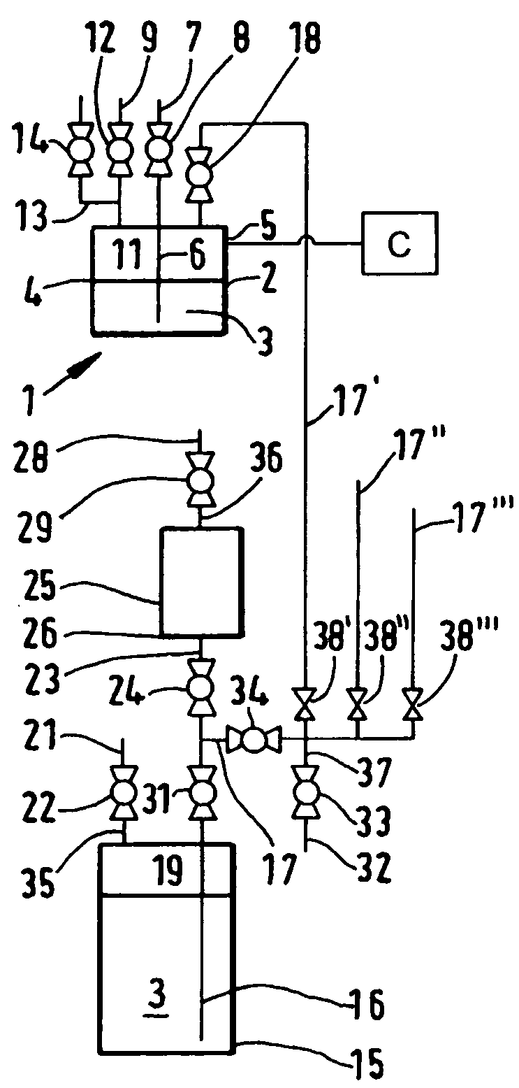
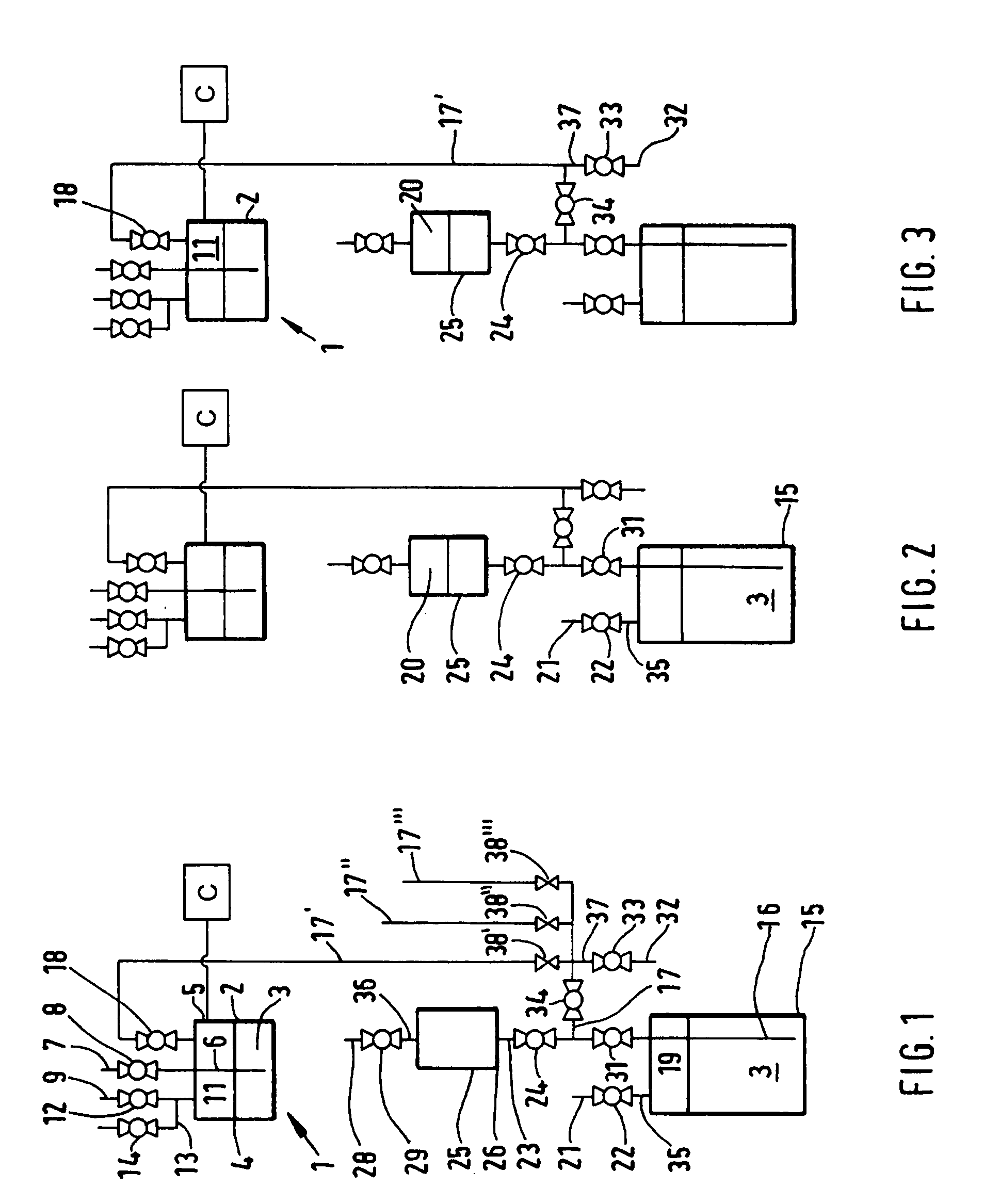
[0029]According to FIG. 1, a bubbler 1 has a tank 2 which is filled with a liquid substance 3, and which in FIG. 1 has a minimum level 4, detected by a level sensor 5.

[0030]Immersed in the liquid substance 3 is an immersion tube 6, through which a carrier gas is conveyed into the liquid substance 3 by means of a carrier gas line 7 with a valve 8, for the evaporation of the liquid substance 3.

[0031]The evaporated liquid substance 3 is conveyed via a supply line 9 to a user, not shown, e.g. a CVD reactor. The supply line 9 connected to the gas chamber 11 of the bubbler 1 has a valve 12. Between the gas chamber 11 and the valve 12, a gas discharge line 13 with a valve 14 is connected to the supply line 9.

[0032]The liquid substance 3 for refilling the bubbler 1 is stored in a reservoir tank 15. Immersed in the liquid substance 3 in the reservoir tank 15 is an immersion tube 16, which is connected by a connection line 17 with the gas chamber 11 of the bubbler 1, with a filling valve 18 b...


PUM

PropertyMeasurementUnit
Pressureaaaaaaaaaa
Levelaaaaaaaaaa
Hydrostatic pressureaaaaaaaaaa

Abstract

In order to evaporate a liquid substance (3) and convey it to a user, a bubbler (1) is provided, into which a carrier gas (7) is conveyed. When a minimum level (4) has been reached, an exact quantity of the substance (3) is refilled from a reservoir tank (15). For this purpose, an intermediate tank (25) is provided, which is filled with an inert gas up to a pressure P1. An inert gas (21) is applied to the reservoir tank (15) at a pressure P2, higher than P1. The intermediate tank (25) is connected with the reservoir tank (15), as a result of which a specific quantity of the substance (3) flows into the intermediate tank (25) and is conveyed via a connection line (17) to the bubbler (1), with inert gas (32) first having been applied to the connection line (17) at a pressure P3, lower than P2.

Description

FIELD OF THE INVENTION[0001]The invention relates to an apparatus and process for refilling a bubbler used to convey a carrier gas into a liquid substance in order to evaporate the substance and supply it to a user, according to the generic part of claims 1 and 9.BACKGROUND OF THE INVENTION[0002]Such an apparatus and process is already known. The user may be, for example, a reactor for chemical vapor deposition (CVD). Such CVD reactors are used in the manufacture of integrated microcircuits and similar electronic components. To meet the increasingly rigorous requirements for such components, substances of very high purity must be used for the chemical vapor deposition process. The substances involved are usually organic metallic and semi-metallic compounds in liquid form.[0003]In addition to the requirement for very high purity, it is also important to ensure precise compliance with the specified gas mixture composition in the CVD reactor, and therefore a consistent quantity of the ...

Claims


Application Information

Patent Timeline
IPC IPC(8): F17D1/16B01J4/02B01B1/00B01J7/02C23C16/448F04F1/06G01F11/28G05D9/04G05D9/12
CPCB01B1/005G05D9/12C23C16/4482Y10T137/0396Y10T137/3127A61H9/0057A61H2205/082
Inventor SCHOLZ, CHRISTOPH
Owner CSK INC
Why Eureka
Try Eureka