Swaged cable deployment in space

a technology of swaged cables and deployment systems, applied in the field of deploying objects in space, can solve problems such as sleeve tear, and achieve the effects of preventing cable splaying, reducing sleeve tear, and reducing sleeve tear

Active Publication Date: 2007-10-09
LOCKHEED MARTIN CORP
View PDF9 Cites 15 Cited by
  • Summary
  • Abstract
  • Description
  • Claims
  • Application Information

AI Technical Summary

Benefits of technology

[0014]When a physical cutter is used to cut a wire rope cable, the wires (i.e., strands) of the cable tend to splay or unravel. To substantially eliminate such splaying of the cable, the wire rope cable that may be used by the present invention has a sleeve that is swaged onto a portion of the cable. The swaging of the sleeve onto the cable causes the sleeve to compress into the “grooves of the wire rope and form a mechanical bond to the cable. The swaged sleeve maintains the integrity of the wire rope cable when the cable is cut through the sleeve. For example, the swaged sleeve performs as a band that restrains the wires of the cable from splaying when the cable is cut because of the mechanical bond between the sleeve and the wires of the cable.
[0015]The swaged portion of the wire rope cable is preferably a malleable metal such as copper. The sleeve is swaged onto the cable with a force that forms a mechanical bond between the sleeve and the cable. The resultant mechanical bond may become stronger than the material of the sleeve itself. For example, the mechanical bond is so strong that removing the sleeve from the cable would require tearing the sleeve. The mechanical bond of the sleeve to the cable substantially prevents cable splaying and substantially reduces the amount of debris that typically result from cutting a wire rope cable. In addition to the reduced debris and splaying, the swaging process typically requires less cleaning of the wire rope cable and specifically eliminates the need to clean the cable with an ODC.

Problems solved by technology

For example, a force required to pull the sleeve from the cable may result in a tear of the sleeve material.

Method used


Image

  • Swaged cable deployment in space
  • Swaged cable deployment in space
  • Swaged cable deployment in space

Examples


Embodiment Construction

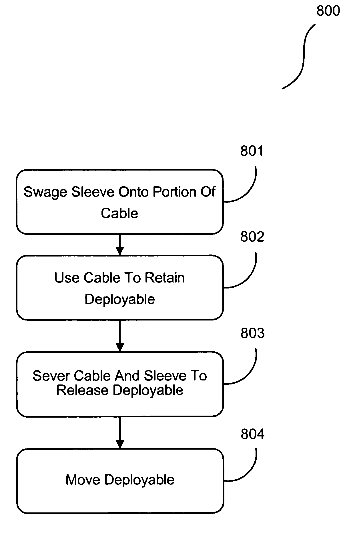
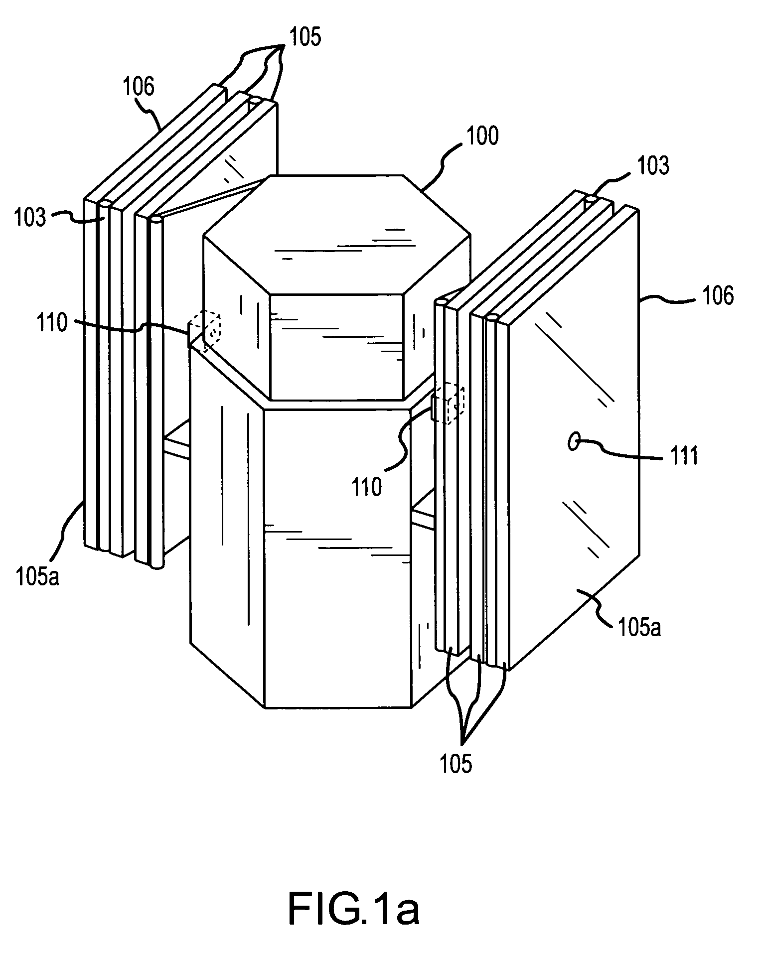
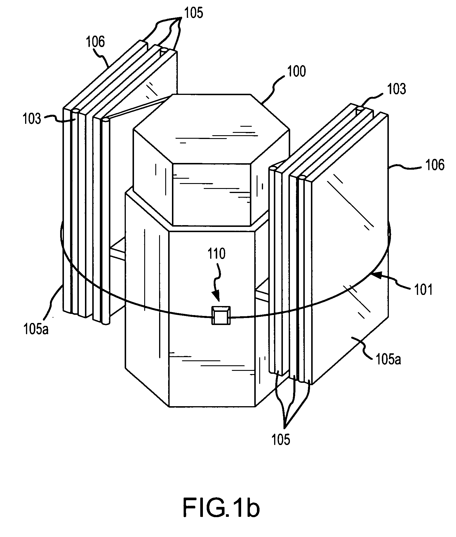
[0026]FIGS. 1a, 1b and 2 illustrate a spacecraft 100 with a solar panel array 106 restrained by a cable restraint / deployment mechanism 110. FIGS. 1a and 1b are perspective views of spacecraft 100 with solar panel array 106 restrained in a stowed position by cable restraint / deployment mechanism 110. In this embodiment, the stowed position is such that panels 105 of array 106 are folded upon one another. Cable restraint / deployment mechanism 110 may restrain the panels 105, for example, until placement of spacecraft 100 in an orbit. Upon placement in orbit, spacecraft 100 may deploy the solar panel array 106 using cable restraint / deployment mechanism 110.

[0027]The cable restraint / deployment mechanism 110 uses cable 101 (shown below in FIGS. 2 and 3) to restrain solar panel array 106 until deployment. In this embodiment, cable 101 is a wire rope cable as is well-known to those skilled in the art. Cable 101 is threaded through panels 105 via cable guides 104 and is affixed at one end to ...


PUM

PropertyMeasurementUnit
thicknessaaaaaaaaaa
diameteraaaaaaaaaa
diameteraaaaaaaaaa

Abstract

A cable restraint/deployment mechanism is disclosed for deploying an object in space from a spacecraft. To deploy the object, the cable restraint/deployment mechanism cuts a cable attached to the spacecraft and the object. For example, a spacecraft may include a solar panel array that is restrained by the spacecraft in a stowed form through the use of a wire rope cable. The cable may be affixed at one end to a deployable object. The other end of the cable is affixed to the spacecraft through a cutting mechanism, such as a pyrotechnically actuated cutting device. The cutting mechanism cuts the cable at a swaged sleeve of the cable. The swaged sleeve of the cable substantially prevents splaying of the cable and cutting debris.

Description

CROSS REFERENCE TO RELATED APPLICATIONS[0001]This patent application is related and claims priority to U.S. Provisional Patent Application No. 60 / 527,176 that is entitled “Copper Sleeved Restraint Cables”, that was filed Dec. 5, 2003 and the entire contents of which are incorporated by reference herein.FIELD OF THE INVENTION[0002]The present invention generally relates to the field of deploying objects in space and, more particularly, to a cable restraint and deployment system for operably deploying an object such as an antenna array or a solar panel array from a spacecraft.BACKGROUND OF THE INVENTION[0003]Cable restraint / deployment systems exist in a variety of configurations for deploying an object in space. Typically these restraint / deployment systems use a wire rope cable with one end affixed to a spacecraft and the other end affixed to a deployable object, such as a solar panel array of the spacecraft. For example, the solar panel array of the spacecraft may be delivered in spa...

Claims


Application Information

Patent Timeline
Patent Type & Authority Patents(United States)
IPC IPC(8): B64G1/40
CPCB64G1/222B64G1/66B64G1/44Y10T83/222
Inventor MUNDER, JOSEPH C.
Owner LOCKHEED MARTIN CORP
Why Eureka
Try Eureka