Apparatus for reducing entrapment of foreign matter along a moveable shaft of a substrate support

a technology of foreign matter and substrate support, which is applied in the field of apparatus for reducing foreign matter along the moveable shaft of the substrate support, can solve the problems of premature wear and/or failure of the system, complex integrated circuits, and abrasion, and achieve the effect of reducing component wear

Inactive Publication Date: 2007-10-09
APPLIED MATERIALS INC
View PDF11 Cites 6 Cited by
  • Summary
  • Abstract
  • Description
  • Claims
  • Application Information

AI Technical Summary

Benefits of technology

[0009]In one embodiment, a guard ring for reducing particle entrapment along a moveable shaft of a substrate support is provided. In one embodiment, a substantially annular guard ring is positioned within a step formed in a sleeve that circumscribes the shaft. The guard ring is positioned to substantially seal a gap separating the shaft from the sleeve, advantageously reducing component wear due to particulate entrapment.
[0010]In another embodiment, a guard ring comprises a base portion having an inner perimeter and an outer perimeter, a first flange coupled to the inner perimeter, a second flange coupled to the outer perimeter, and a continuous channel separating the first flange from the second flange. The first flange is adapted to bias the ring against the shaft, thereby accommodating displacement and / or misalignment of the shaft relative to the processing chamber.

Problems solved by technology

Integrated circuits have evolved into complex devices that can include millions of transistors, capacitors and resistors on a single chip.
The accumulation of particles between the shaft and sleeve can damage both components, leading to premature wear and / or failure of the system.
However, standard o-rings are subjected to abrasion by particulates disposed on the shaft, and thus may not effectively seal the gap after a period of use.
Furthermore, standard o-rings tend to generate particles when subjected to processing chamber conditions, exacerbating the particle entrapment problem rather than solving it.

Method used


Image

  • Apparatus for reducing entrapment of foreign matter along a moveable shaft of a substrate support
  • Apparatus for reducing entrapment of foreign matter along a moveable shaft of a substrate support
  • Apparatus for reducing entrapment of foreign matter along a moveable shaft of a substrate support

Examples


Embodiment Construction

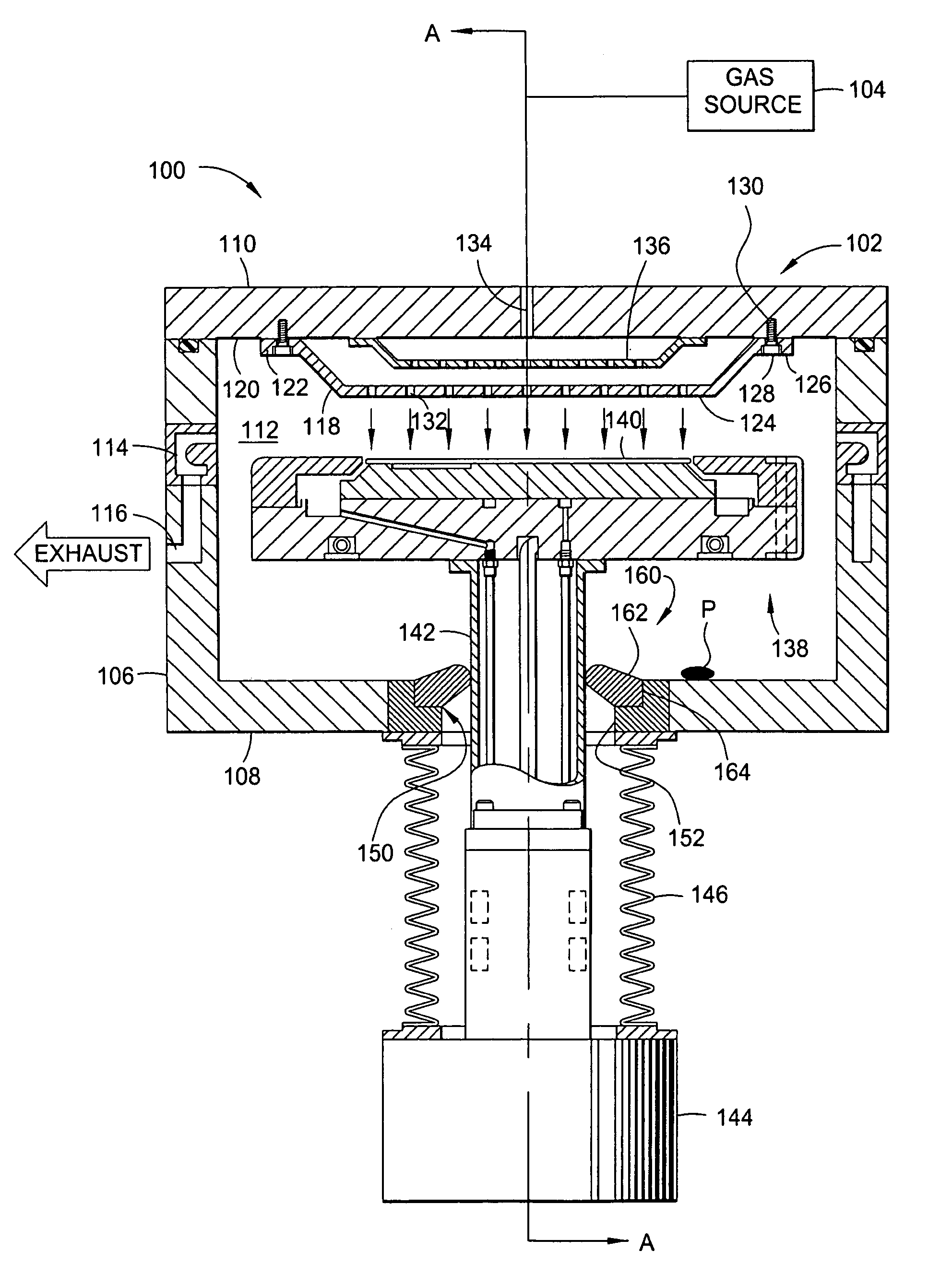
[0025]The invention is a guard ring for preventing particle entrapment along a moveable shaft of a substrate support. The invention is illustratively described below as deployed in a chemical vapor deposition system, such as a barrier chemical vapor deposition (BCVD) system, available from Applied Materials, Inc. of Santa Clara, Calif. However, it should be understood that the invention has utility in other system configurations such as physical vapor deposition systems, ion implant systems, etch systems, chemical vapor deposition systems and any other wafer processing system in which the reduction of particle damage to a moving shaft is necessary or desirable.

[0026]FIG. 1 is a cross-sectional view of one embodiment of a chemical vapor deposition system 100 that is advantageously adapted to benefit from the present invention. The system 100 generally includes a chamber body 102 coupled to a gas source 104. The chamber body 102 has walls 106, a bottom 108 and a lid 110 that define a ...


PUM

PropertyMeasurementUnit
frequencyaaaaaaaaaa
temperatureaaaaaaaaaa

Abstract

In one embodiment, the invention is a guard ring for reducing particle entrapment along a moveable shaft of a substrate support. In one embodiment, the guard ring comprises a substantially annular guard ring positioned within a step formed in a sleeve that circumscribes the shaft. The guard ring is positioned to substantially seal a gap separating the shaft from the sleeve, so that the amount of particles and foreign matter that travel within or become trapped in the gap is substantially reduced. In another embodiment, a guard ring comprises a base portion having an inner perimeter and an outer perimeter, a first flange coupled to the inner perimeter, a second flange coupled to the outer perimeter, and a continuous channel separating the first flange from the second flange. The first flange is adapted to function as a spring that accommodates displacement of the shaft.

Description

BACKGROUND OF THE DISCLOSURE[0001]1. Field of Invention[0002]The invention relates generally to the processing of semiconductor wafers, and relates more particularly to an apparatus for reducing entrapment of foreign matter along a moveable shaft of a substrate support.[0003]2. Background of the Invention[0004]Integrated circuits have evolved into complex devices that can include millions of transistors, capacitors and resistors on a single chip. The evolution of chip designs continually requires faster circuitry and greater circuit density that demand increasingly precise fabrication techniques and processes. One fabrication process frequently used is chemical vapor deposition (CVD). Chemical vapor deposition is generally employed to deposit a thin film on a substrate or a semiconductor wafer.[0005]Chemical vapor deposition is generally accomplished by introducing a precursor gas into a vacuum chamber. The precursor gas is typically directed through a showerhead situated near the t...

Claims


Application Information

Patent Timeline
Patent Type & Authority Patents(United States)
IPC IPC(8): C23C16/00C23F1/00H01L21/306C23C16/44H01L21/00
CPCH01L21/67126C23C16/4401
Inventor KASZUBA, ANDRZEJVELASTEGUI, SOPHIA M.SIVARAMAKRISHNAN, VISWESWARENYIM, PYONGWONSILVETTI, MARIO DAVIDCHO, TOM K.LAHIRI, INDRAJITBEDI, SURINDER S.
Owner APPLIED MATERIALS INC
Why Eureka
Try Eureka