Filter device

a filter device and filter technology, applied in the direction of filtering separation, moving filter element filters, separation processes, etc., can solve the problems of unfavorable flow conditions, damage to the hydraulic system, adversely affecting the filtration performance of the known device, etc., and achieve the effect of low production and maintenance costs

Inactive Publication Date: 2007-10-09
HYDAC FILTERTECHNIK GMBH
View PDF14 Cites 8 Cited by
  • Summary
  • Abstract
  • Description
  • Claims
  • Application Information

AI Technical Summary

Benefits of technology

[0006]Objects of the present invention are to provide an improved filter device with a bypass device, while maintaining the advantages in the prior art. Specifically, even in the case of triggering of the bypass device (bypass), damage of any type to the overall hydraulic system is avoided such that an especially compressively-still structure for the entire filter element configuration is ensured, and such that the flow conditions in filter operation are favorable with simultaneously low production and maintenance costs.
[0007]These objects are achieved by a filter device where the second filter element has an installation length which is shortened by at least one-half compared to the first filter element. Because the second filter element projects into the first filter element to the extent that its top end cap lies essentially in one plane transversely to the middle lengthwise axis with the top end of the fluid inlet which extends laterally through the filter housing, there is an especially compressively-still structure for the entire filter element configuration with respect to the radial inflow of the medium to be filtered by way of the fluid inlet. Since this compressively-stiff structure is implemented without further aids, such as a protective jacket or the like, the production costs and maintenance costs are reduced accordingly when the filter elements are replaced by new ones. The medium to be filtered flows through the first filter element essentially in the radial direction, originating from the fluid inlet on the side filter housing, and travels filtered to the other, second filter element. As a result of the radial direction of flow through the filter elements the flow conditions are favorable for the fluid which is to be filtered within the filter element system. Furthermore, the pertinent configuration with different overall lengths enables compact accommodation of the bypass valve in the end area of the first filter element.
[0008]The configuration is such that with the triggering and opening of the bypass device (bypass), the second filter element directly undertakes filtration of the fouled medium, so that primary filtration shifted to the second filter element can take place at the same time. Connecting the two filter elements in succession in the conventional flow direction of the medium moreover ensures that in case of failure of the first filter element, which is otherwise available for primary filtration, for example, in the case of bursting or when the filter mat tears or the like, the following second filter element ensures filtration so that in the pertinent case dirt cannot enter the hydraulic circuit and cause damage. These safety functions play an important role, especially when these filter elements are used in the area of bearing lubrication in wind power plants, in high rotation paper printing machines or the like.
[0010]In another, especially preferred embodiment of the filter device of the present invention, the two filter elements are arranged coaxially relative to one another, and extend along the middle lengthwise axis of the filter housing. This arrangement yields an overall filter device with a very compact structure. Also, the two filter elements can be easily and quickly replaced in the sense of a modularly structured replacement set as a whole. This capability reduces production costs and also maintenance costs.
[0013]When using two filter elements, it has proven especially advantageous to provide the first filter element with a filter mesh fineness of 10 μm and to equip the second filter element which follows in the flow direction with a filter mesh fineness of approximately 200 μm.

Problems solved by technology

Unwanted pressure rises can otherwise lead to damage within the hydraulic system.
Solely due to the protective jacket and the axial alignment of the fluid inlets parallel to the middle lengthwise axis of the filter housing unfavorable flow conditions arise.
This arrangement adversely affects filtration performance with the known device in normal filter operation.
The attachment of the protective jacket requires on the one hand installation space within the filter device and on the other hand leads to corresponding additional costs in production and maintenance.

Method used


Image

  • Filter device
  • Filter device

Examples


Embodiment Construction

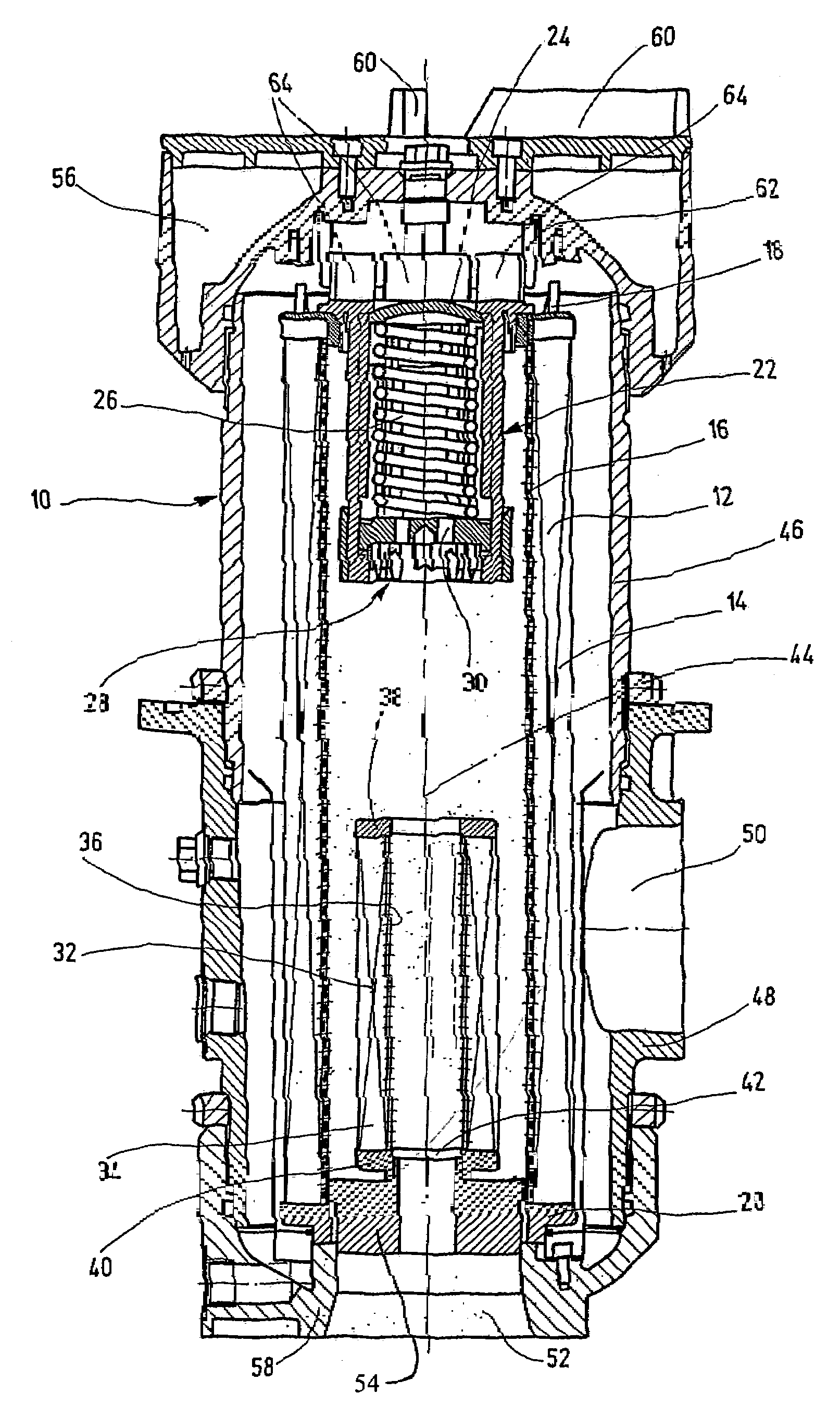
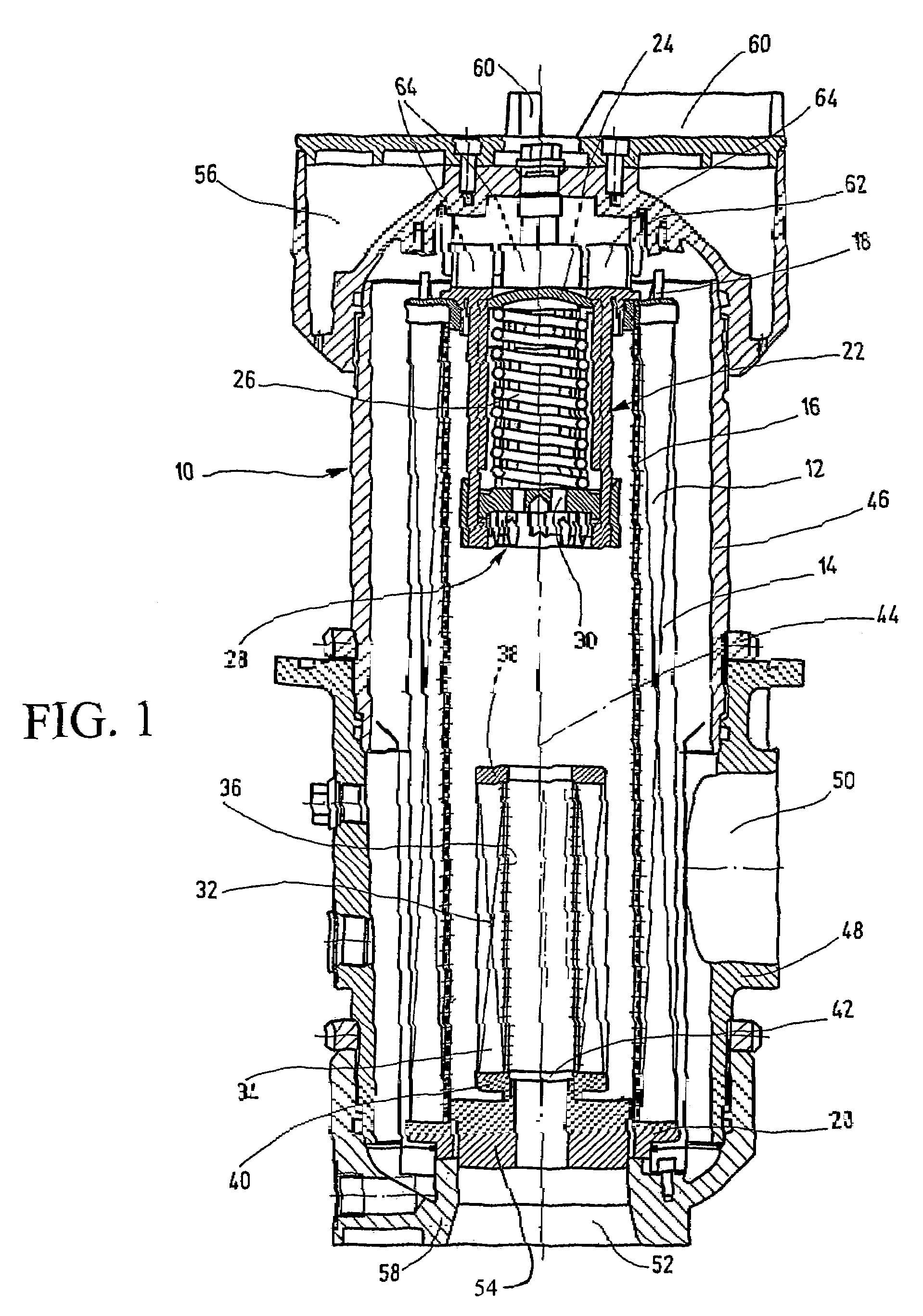
[0017]The filter device has a filter housing 10 receiving a first filter element 12. The filter element 12 forms a hollow cylinder. Its filter mat 14 is pleated in the conventional manner (not shown), and encompasses a support tube 16 with fluid passages. The support tube 16 itself is made as a hollow cylinder. The support tube configuration ensures that, for the direction of flow through the first filter element 12 from the outside to the inside, the filter mat 14 can be effectively supported on the support tube 16 and, for example, does not bulge to the inside and possibly begin to tear. On the two ends of the filter element 12, the filter element is provided with end caps 18 and 20, by way of which the filter element 12 is held within the filter housing 10. The respective end caps 18 and 20 are connected fluid-tight to one another by way of the corresponding cementing and / or sealing means with the free ends of the support tube 16 and of the filter mat 14 of the first filter eleme...


PUM

PropertyMeasurementUnit
particle diameteraaaaaaaaaa
lengthaaaaaaaaaa
lengthsaaaaaaaaaa

Abstract

A filter device has a filter housing (10) receiving a first filter element (12), through which a medium may flow in a given direction, and has a bypass device (22). Along with the first filter element (12), a second filter element (32) is provided. The filter elements are arranged in series, one behind the other, in the direction of flow. When the bypass device (22) is activated, the second filter element (32), immediately following in the direction of flow, filters the medium. The second filter element thus takes over the main filtration of the medium on actuation and operation of the bypass device, since the first filter element is essentially no longer available for a filtration process due to the bypass device.

Description

FIELD OF THE INVENTION[0001]The present invention relates to a filter device having a filter housing with a first filter element located therein and through which a medium flows with a definable direction, and having a bypass device.BACKGROUND OF THE INVENTION[0002]Comparable filter devices (see, e.g., FR-A-1 415 943 and U.S. Pat. No. 3,000,505) are known in a plurality of embodiments and sizes. Within the filter housing, generally at least one hollow-cylindrical filter element removes impurities from fouled liquid supplied through an inlet into the filter housing. Flow takes place through the respective filter element from the outside to the inside. The filtering filter mat of the filter element is supported along a support tube provided with passages. The liquid which has been filtered in this way is then drained through an outlet in the filter housing for further use. The longer the filter element is in operation for filtration, the more it is clogged by dirt until finally the fi...

Claims


Application Information

Patent Timeline
Patent Type & Authority Patents(United States)
IPC IPC(8): B01D35/14B01D27/10B01D29/21B01D35/147
CPCB01D29/21B01D35/147B01D29/54B01D29/58B01D29/96B01D35/301B01D2201/188B01D2201/301B01D2201/313
Inventor SANN, NORBERTWILKENDORF, WERNER
Owner HYDAC FILTERTECHNIK GMBH
Why Eureka
Try Eureka